Biophotonic measurement device and method
a biophotonic and measurement device technology, applied in the field of biophotonic measurement devices, can solve the problems of increasing, difficult to realize, and difficult to reduce the cost of the device supporting the application of small nirs, and achieve the effect of high signal-to-noise ratio and high precision of biophotonic measuremen
- Summary
- Abstract
- Description
- Claims
- Application Information
AI Technical Summary
Benefits of technology
Problems solved by technology
Method used
Image

Examples
first embodiment
[0030]A first embodiment is an embodiment of a biophotonic measurement device including: a photoirradiation unit for radiating light to a photoirradiation point; a photodetection unit for detecting the light, which is radiated from the photoirradiation unit, at a photodetection point; and a processing unit which processes detection output of the photodetection unit, wherein the processing unit is configured to switch signal detection methods between the photoirradiation unit and the photodetection unit by utilizing evaluation function values determined by the detection output of the photodetection unit.
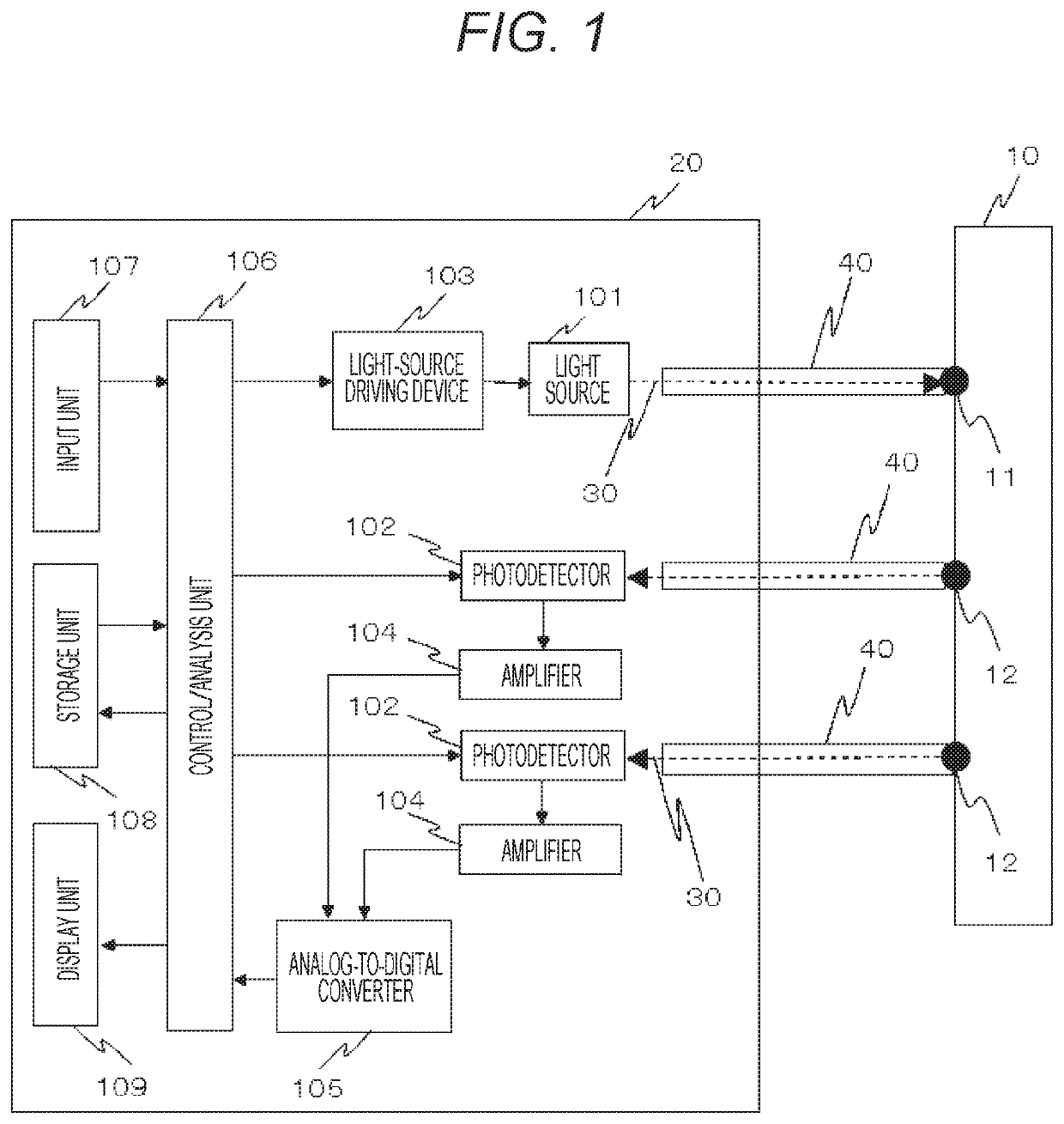
[0031]FIG. 1 shows an example of an overall configuration of a biophotonic measurement device of the present embodiment. In the biophotonic measurement device capable of injecting light into a biological body and detecting the light scattered / absorbed and propagated in the biological body and released to outside the biological body, light 30 radiated from a light source(s) 101, which ...
second embodiment
[0067]Next, as a second embodiment, an embodiment about a method of determining an optimum intensity modulation frequency as the signal detection method of the combinations of the measurement points or the light sources and the detectors will be described. In the present embodiment, at the same time, in signal demodulation by a lock-in method such as the continuous light lock-in method as the signal detection method, automatic acquisition of optimum delay time, wherein the delay time of a reference signal subjected to multiplication of the detection signal, will be also described.
[0068]FIG. 13 shows a flow chart of automatic acquisition of an optimum intensity modulation frequency and optimum delay time. R types of delay time n are prepared (step S131). The delay time may be manually or automatically input from the input unit 107. Then, 1 is substituted for n (step S132). Among the R types of delay time, the n-th delay time is set for the reference signal of the lock-in of detection...
third embodiment
[0070]A third embodiment is an embodiment about a method of determining the number of measurement channels as the signal detection method by quality evaluation of measurement signals in the biophotonic measurement device. FIG. 14 shows a flow chart in a case of determination of the number of the measurement channels as the signal detection method by quality evaluation of the signals of the present embodiment. As shown in this view, first, the light sources to be used are acquired and listed, and a priority order thereof is determined (order 1 to N) (step S141). The order may be input in advance depending on the part and channel positions. Then, 1 is substituted for n (step S142).
[0071]The light source of the n-th priority order and all the light sources having the priority order higher than n are lit by the continuous light measurement method, and the light propagated in the biological body is detected (step S143). The quality of the detected signals is evaluated (step S144). Whethe...
PUM
| Property | Measurement | Unit |
|---|---|---|
| distance | aaaaa | aaaaa |
| distance | aaaaa | aaaaa |
| threshold | aaaaa | aaaaa |
Abstract
Description
Claims
Application Information
 - R&D
- Intellectual Property
- Life Sciences
- Materials
- Tech Scout
- Unparalleled Data Quality
- Higher Quality Content
- 60% Fewer Hallucinations
Browse by: Latest US Patents, China's latest patents, Technical Efficacy Thesaurus, Application Domain, Technology Topic, Popular Technical Reports.
© 2025 PatSnap. All rights reserved.Legal|Privacy policy|Modern Slavery Act Transparency Statement|Sitemap|About US| Contact US: help@patsnap.com