
Variable compression ratio apparatus

a compression ratio and variable technology, applied in the direction of cranks, shafts and bearings, eccentrics, etc., can solve the problems of weakening the durability of links, limiting the corresponding degradation of output, and limiting the advancing ignition timing, so as to reduce the cost, prevent the interference of rotational inertia, and the effect of variable compression ratio

Active Publication Date: 2019-11-26
HYUNDAI MOTOR CO LTD +1
View PDF17 Cites 3 Cited by
  • Summary
  • Abstract
  • Description
  • Claims
  • Application Information

AI Technical Summary

Benefits of technology

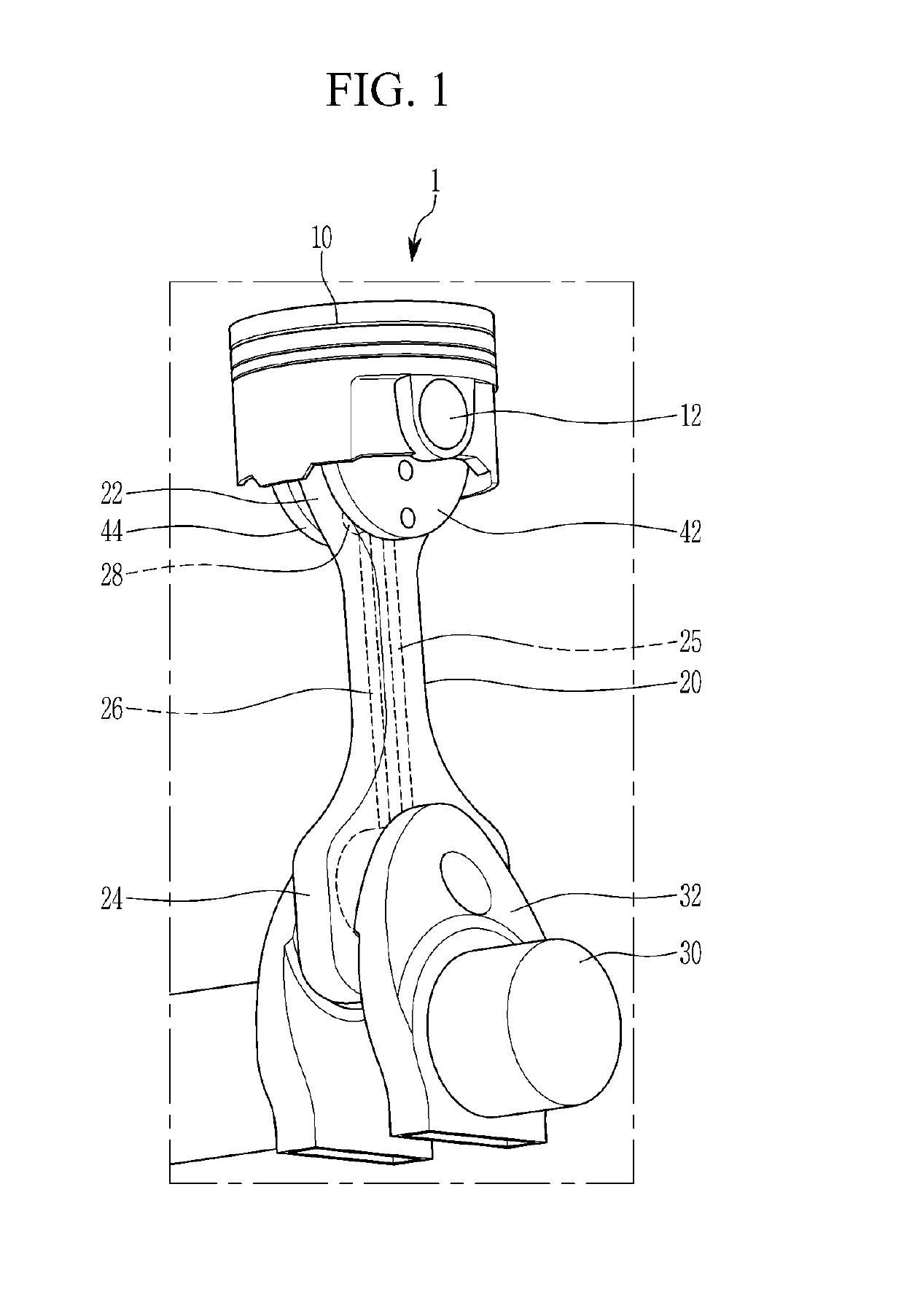
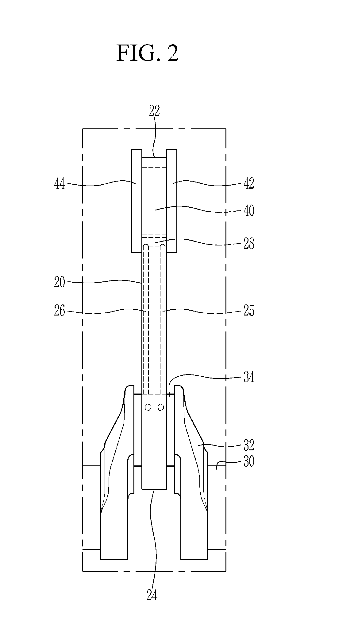
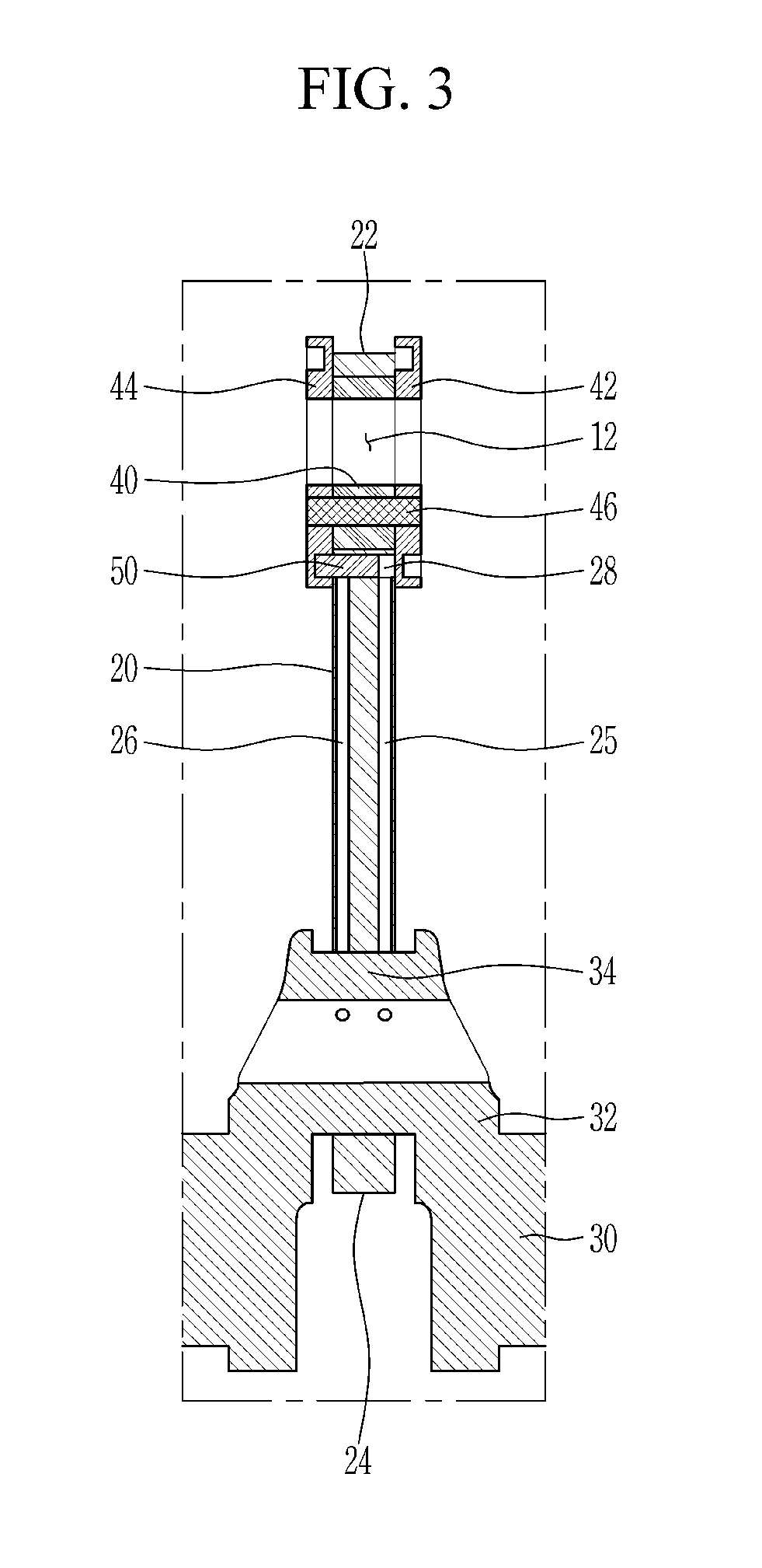
The present invention provides a variable compression ratio apparatus which can change the compression ratio of a mixture by installing an eccentric cam in a small end portion of a connecting rod and selectively latching the eccentric cam in different positions. The apparatus can also prevent interference and reduce cost by using a simplified latching pin. The apparatus allows for the achievement of low compression ratio conditions by inserting the latching pin into a first latching groove or high compression ratio conditions by inserting the latching pin into a second latching groove. The apparatus may also include a stopper to limit the rotation of the eccentric cam.

Problems solved by technology

However, when ignition timing of a spark ignition engine is advanced at a high compression ratio, abnormal combustion occurs to damage the engine, causing a limitation in advancing the ignition timing and a corresponding degradation of output should be tolerated.
Thus, durability of the links weakens.
Meanwhile, when hydraulic pressure is used to rotate an eccentric cam, an amount of rotation and an amount of hydraulic outflow of the eccentric cam of each cylinder are different, resulting in a compression ratio of each cylinder that is not uniform and a time during which a compression ratio is changed varies according to engine operational conditions.
Further, control of latching an eccentric cam may become more difficult.

Method used


Image

  • Variable compression ratio apparatus
  • Variable compression ratio apparatus
  • Variable compression ratio apparatus

Examples


Embodiment Construction

[0067]It is understood that the term “vehicle” or “vehicular” or other similar term as used herein is inclusive of motor vehicles in general such as passenger automobiles including sports utility vehicles (SUV), buses, trucks, various commercial vehicles, watercraft including a variety of boats and ships, aircraft, and the like, and includes hybrid vehicles, electric vehicles, combustion, plug-in hybrid electric vehicles, hydrogen-powered vehicles and other alternative fuel vehicles (e.g. fuels derived from resources other than petroleum).

[0068]The terminology used herein is for the purpose of describing particular embodiments only and is not intended to be limiting of the invention. As used herein, the singular forms “a”, “an” and “the” are intended to include the plural forms as well, unless the context clearly indicates otherwise. It will be further understood that the terms “comprises” and / or “comprising,” when used in this specification, specify the presence of stated features,...


PUM


Abstract

A variable compression ratio apparatus is provided and is installed within an engine rotating a crankshaft upon receiving combustion power of a mixture from a piston and changes a mixture compression ratio based on an engine driving condition. The apparatus includes a connecting rod at which a small end forming a circular aperture to be rotatably connected with a piston pin moving together with the piston, a larger end rotatably connected with a crankpin eccentrically arranged with respect to the crankshaft, and an acting oil passage formed to supply hydraulic pressure from the larger end to the small end, are formed. An eccentric cam is concentrically arranged and rotatably disposed in the small end aperture and the piston pin is eccentrically inserted thereinto and is rotatably connected therewith. A latching pin selectively latches the small end with the cam by supply of hydraulic pressure through the acting oil passage.

Description

CROSS-REFERENCE TO RELATED APPLICATION[0001]This application claims priority to and the benefit of Korean Patent Application No. 10-2018-0090952 filed on Aug. 3, 2018, the entire contents of which are incorporated herein by reference.BACKGROUND(a) Field of the Invention[0002]The present invention relates to a variable compression ratio apparatus, and more particularly, to a variable compression ratio apparatus in which a compression ratio of a mixture in a combustion chamber is varied according to an operational state of an engine.(b) Description of the Related Art[0003]Generally, heat efficiency of a compression ignition engine is increased when a compression ratio is high, and for a spark ignition engine, when ignition timing is advanced to a particular level, heat efficiency is increased. However, when ignition timing of a spark ignition engine is advanced at a high compression ratio, abnormal combustion occurs to damage the engine, causing a limitation in advancing the ignition ...

Claims


Application Information

Patent Timeline
Patent Type & Authority Patents(United States)
IPC IPC(8): F02B75/04F16C3/28F02D15/02
CPCF16C3/28F02B75/047F02D15/02F02B75/048F02B75/045F16C7/06
Inventor CHOI, MYUNGSIK
Owner HYUNDAI MOTOR CO LTD
Learn More