Monolithic ceramic capacitor and structure for mounting the same
a technology of monolithic ceramic capacitors and structures, applied in the direction of fixed capacitors, stacked capacitors, fixed capacitor details, etc., can solve the problems of reducing insulation resistance, structural defects not necessarily serving, etc., and achieve high moisture resistance reliability and reduce costs
- Summary
- Abstract
- Description
- Claims
- Application Information
AI Technical Summary
Benefits of technology
Problems solved by technology
Method used
Image
Examples
first embodiment
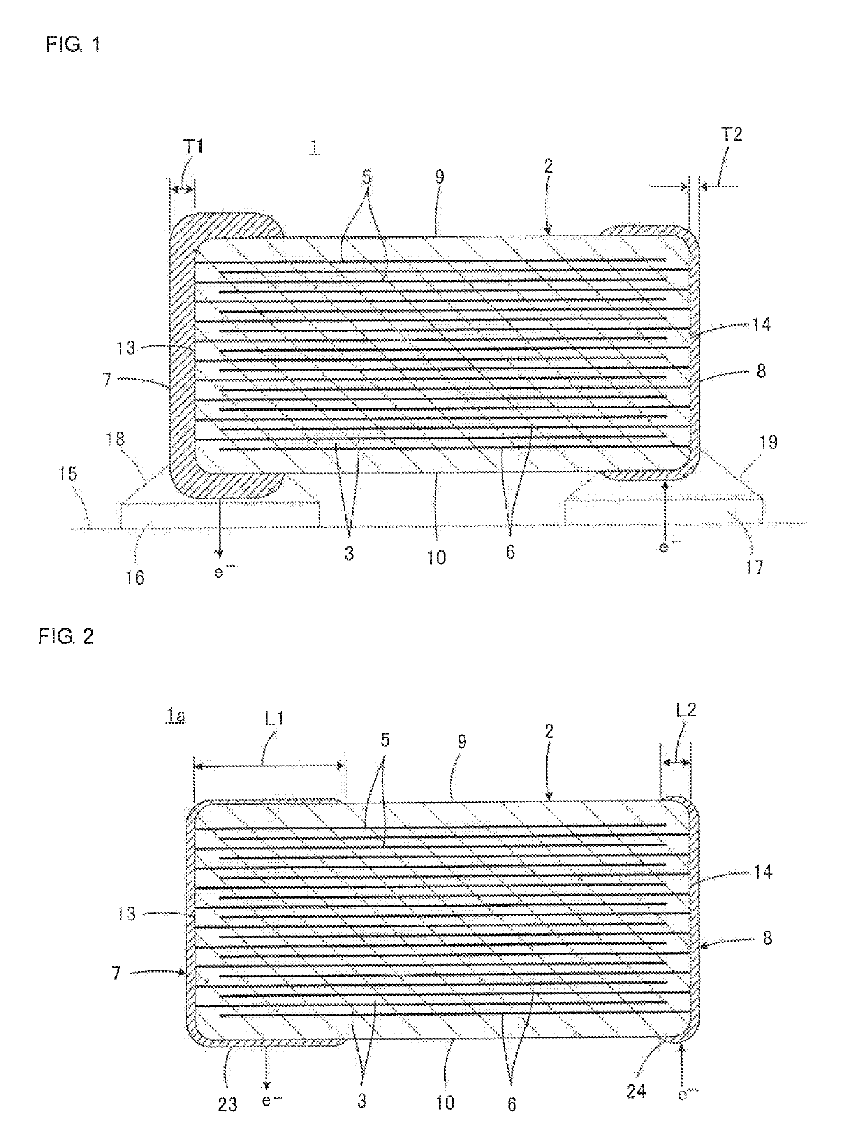
[0053]Referring to FIG. 1, a monolithic ceramic capacitor 1 according to the present invention will be described.
[0054]The monolithic ceramic capacitor 1 includes a multilayer body 2 which is a main body. The multilayer body 2 includes a plurality of dielectric ceramic layers 3 and inner electrodes (first inner electrodes 5 and second inner electrodes 6). The plurality of dielectric ceramic layers 3 are stacked on one another. Each of the inner electrodes is disposed along a corresponding one of a plurality of interfaces between the dielectric ceramic layers 3. A first outer electrode 7 and a second outer electrode 8 are respectively disposed at a first position and a second position on a surface of the multilayer body 2, the first and second positions being different positions, the surface of the multilayer body 2 being a surface that extends in a direction in which the dielectric ceramic layers 3 are stacked on one another.
[0055]More specifically, the multilayer body 2 has a subst...
second embodiment
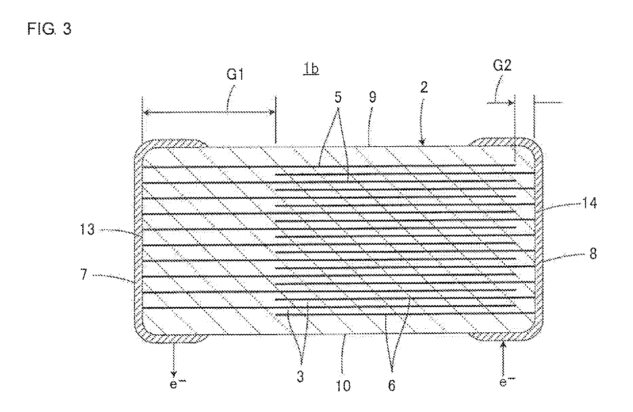
[0082]Referring to FIG. 2, a monolithic ceramic capacitor 1a according to the present invention will be described. In FIG. 2, components equivalent to the components illustrated in FIG. 1 are denoted by similar reference numerals so as to omit a duplicate description.
[0083]In the monolithic ceramic capacitor 1a, the first outer electrode 7 includes an adjacent-surface extending portion 23 that is formed so as to extend from the first end face 13 of the multilayer body 2 to the first and second principle surfaces 9 and 10 and the first and second side faces that are adjacent to the first end face 13. The second outer electrode 8 includes an adjacent-surface extending portion 24 that is formed so as to extend from the second end face 14 of the multilayer body 2 to the first and second principal faces 9 and 10 and the first and second side faces that are adjacent to the second end face 14. Note that the monolithic ceramic capacitor 1 described above also has this configuration.
[0084]Th...
third embodiment
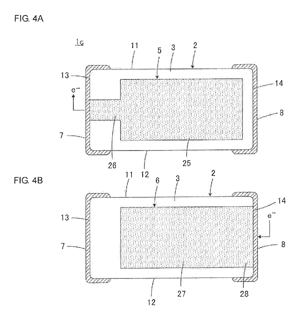
[0086]Referring to FIG. 3, a monolithic ceramic capacitor 1b according to the present invention will be described. In FIG. 3, components equivalent to the components illustrated in FIG. 1 are denoted by similar reference numerals so as to omit a duplicate description.
[0087]In the monolithic ceramic capacitor 1b, the first end face 13 and the second inner electrodes 6 are disposed with a first length-direction gap G1 interposed therebetween. The second end face 14 and the first inner electrodes 5 are disposed with a second length-direction gap G2 interposed therebetween. The monolithic ceramic capacitor 1 described above also has this configuration.
[0088]The third embodiment has a feature in which the first length-direction gap G1 is greater than the second length-direction gap G2. This feature implements a moisture-resistance reliability improving means. That is, by making the first length-direction gap G1 greater than the second length-direction gap G2, it is possible to increase a...
PUM
| Property | Measurement | Unit |
|---|---|---|
| thickness | aaaaa | aaaaa |
| thickness T1 | aaaaa | aaaaa |
| thickness | aaaaa | aaaaa |
Abstract
Description
Claims
Application Information
 - R&D
- Intellectual Property
- Life Sciences
- Materials
- Tech Scout
- Unparalleled Data Quality
- Higher Quality Content
- 60% Fewer Hallucinations
Browse by: Latest US Patents, China's latest patents, Technical Efficacy Thesaurus, Application Domain, Technology Topic, Popular Technical Reports.
© 2025 PatSnap. All rights reserved.Legal|Privacy policy|Modern Slavery Act Transparency Statement|Sitemap|About US| Contact US: help@patsnap.com


