Synchronous machine module, vehicle drive and vehicle

a technology of synchronous machine and module, applied in the direction of machines/engines, starter details, electric generator control, etc., can solve the problems of preventing successful purely controlled run-up, requiring additional equipment, and requiring high cost and sensitive electronics. achieve the effect of simple and robus

Active Publication Date: 2019-11-05
ROLLS ROYCE DEUT LTD & CO KG
View PDF8 Cites 1 Cited by
  • Summary
  • Abstract
  • Description
  • Claims
  • Application Information

AI Technical Summary

Benefits of technology

[0009]It is therefore the object to provide an improved synchronous machine module. It is a further object to provide an improved vehicle drive and an improved vehicle. In particular, the vehicle drive is intended to be able to be designed in a robust and compact manner.
[0012]The synchronous machine module according to one embodiment can subsequently be designed in a simple, robust and compact manner since additional installation space for the sensor can be omitted. Furthermore, the synchronous machine module can therefore be designed in a cost-effective and reliable manner.
[0015]In a preferred embodiment, in the synchronous machine module, the detector is for measuring the phase currents of the synchronous machine and / or for detecting a rotational field frequency of the synchronous machine. The instantaneous active power of the synchronous machine can be easily determined by the phase currents and the set space vectors. Detectors for measuring the phase currents are typically provided in synchronous machines anyway for the purpose of regulating the machine, with the result that, advantageously, no additional outlay in terms of apparatus is incurred with respect to these detectors.
[0023]The vehicle in accordance with one embodiment is, in particular, an aircraft. The vehicle has a vehicle drive as described above and / or a synchronous machine module as described above. The vehicle can thus be designed in a simple, robust and compact manner.

Problems solved by technology

However, resolvers together with associated electronics are expensive and sensitive.
Sensorless solutions, in contrast, function only to a limited extent: the combination of a synchronous machine with an internal combustion engine without its own starter, which is intended to be cranked up by the synchronous machine for starting, thus poses additional demands.
In many cases, this prevents successful purely controlled run-up.
A similar problem is sensorless operation of piston compressors using a PMSM.
In the case of lower rotational speeds, sensorless estimation of the rotor position is difficult or impossible on account of the only low induced voltage.
In these rotational speed ranges, the instantaneous rotor position can be identified to a certain degree of accuracy at certain times by suitable test pulses, but this is insufficient in most cases.
A purely controlled run-up in a rotational speed range in which the estimation of the rotor position functions sufficiently accurately by an observer model is problematic.
The torque that can be achieved in this operating range is usually only a fraction of the normal rated torque of the engine, since, even at low countertorques, “tilting” of the engine cannot be avoided and hence the torque immediately drops.
Targeted setting of the torque is likewise not possible in this operating mode.

Method used


Image

  • Synchronous machine module, vehicle drive and vehicle

Examples


Embodiment Construction

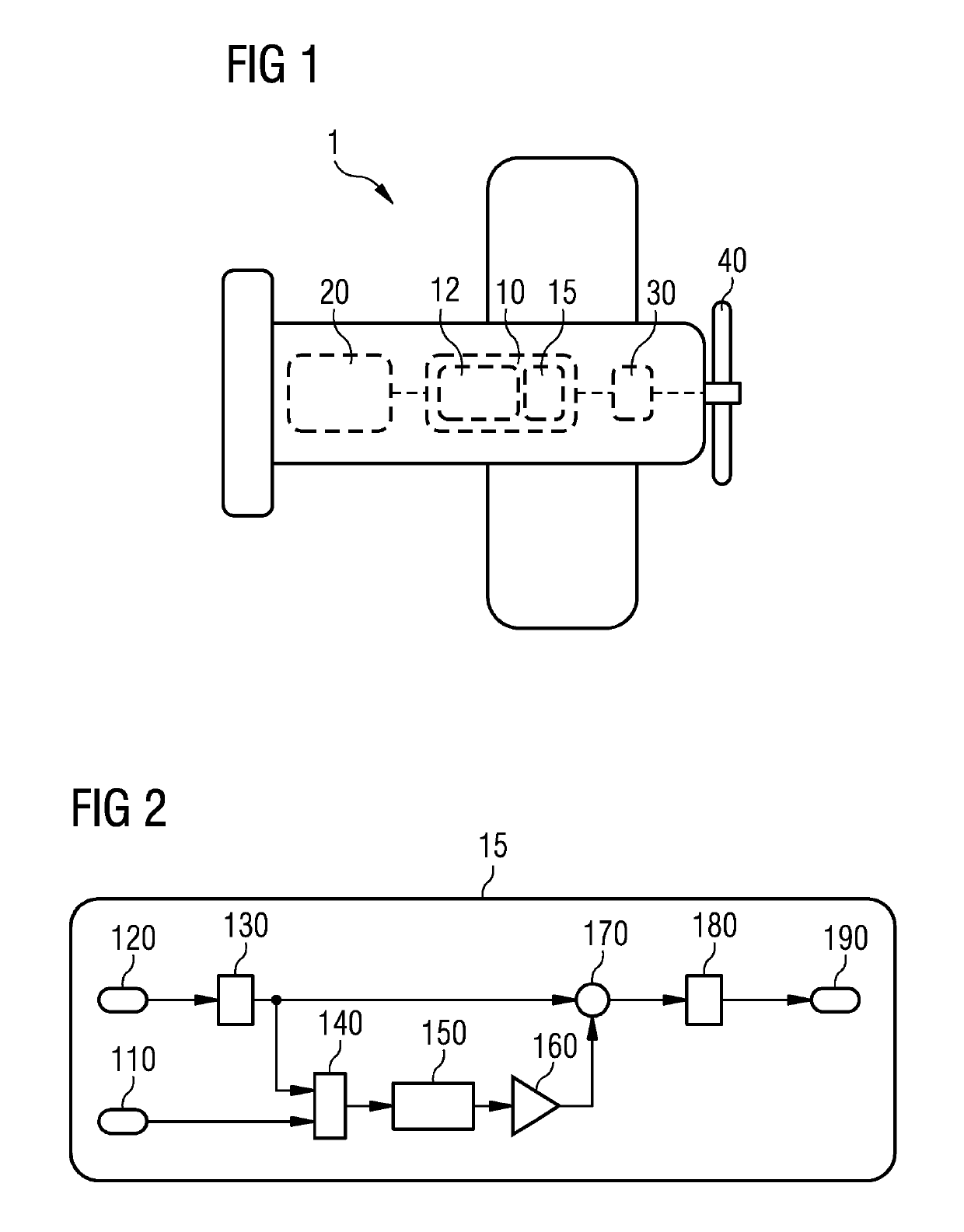
[0029]The vehicle according to the embodiment illustrated in FIG. 1 is a hybrid-electric aircraft 1.

[0030]The hybrid-electric aircraft 1 has a hybrid-electric drive, which includes a synchronous machine module 10 having a permanent-magnet synchronous machine 12 and a rotational speed controller 15 as described below. An internal combustion engine 20 is connected to the drive side of the synchronous machine module 10, said internal combustion engine burning fuel in the state of continuous operation of the aircraft 1 and providing kinetic energy in the form of a rotating shaft in a manner known per se. The rotating shaft is connected to the synchronous machine 12 of the synchronous machine module 10. The synchronous machine 12 is operated in the state of continuous operation by a generator, that is to say the synchronous machine 12 converts the mechanical kinetic energy of the rotating shaft to electrical energy. An electric motor 30 is energized by the electrical energy of the synchr...


PUM


Abstract

The synchronous machine module includes a synchronous machine and a rotational speed controller for controlling a rotational speed of the synchronous machine, which rotational speed controller has a detector for detecting a variable which is formed by the effective power or is dependent thereon. The rotational speed controller is designed to set the rotational speed of the synchronous machine and / or the time profile thereof as a function of the detected variable and / or its time profile. The vehicle drive has such a synchronous machine module and a power generator, which in order to supply the synchronous machine module is connected thereto. The vehicle is, in particular, an aircraft and has such a vehicle drive and / or such a synchronous machine module.

Description

RELATED CASES[0001]The present patent document is a § 371 nationalization of PCT Application Serial Number PCT / EP2016 / 072708, filed Sep. 23, 2016, designating the United States, which claims priority to German Patent Application Serial No. DE 10 2015 218 567.2, filed Sep. 28, 2015, which are hereby incorporated by reference.BACKGROUND[0002]Hybrid-electric drives are currently used in many fields. In particular, internal combustion engines and generators are combined with one another for the purpose of generating electricity. In this case, the generator is intended to be designed in the simplest manner possible and to be as compact and robust as possible.[0003]Permanent-magnet synchronous machines (PMSMs) appear to be particularly suitable for hybrid-electric drives on account of their high power density. However, precise determination of the rotor position is required for efficient operation.[0004]To determine the rotor position, inductive rotary encoders, so-called resolvers, which...

Claims


Application Information

Patent Timeline
Patent Type & Authority Patents(United States)
IPC IPC(8): H02P6/06H02P25/024B64D27/24B64D27/04H02P23/20F02B53/02H02P9/00B64D27/02F02B53/00H02P1/04
CPCH02P6/06H02P25/024F02B53/02H02P1/04H02P23/20B64D27/04B64D27/24B64D2027/026F02B2053/005H02P9/00
Inventor BACHMANN, CHRISTIANBERGMANN, DOMINIKCYRIACKS, MARCOPAIS, GUILLAUMEVITTORIAS, LASON
Owner ROLLS ROYCE DEUT LTD & CO KG
Why Eureka
Try Eureka