Automatically releasable hose reel assembly

a technology of automatic release and hose reel, which is applied in the direction of clutches, mechanical equipment, transportation and packaging, etc., can solve the problems of operator injury, electromechanical drive devices tend to be oversized and underpowered, and operators can inadvertently overlook the need, so as to reduce the load and increase the risk

Active Publication Date: 2017-08-03
SPRAY NOZZLE ENG
View PDF3 Cites 1 Cited by
  • Summary
  • Abstract
  • Description
  • Claims
  • Application Information

AI Technical Summary

Benefits of technology

The invention is a reel assembly with a release mechanism that automatically actuates when the hose is tensioned for payout. The release mechanism is simple, compact and in a mechanical form, avoiding the use of existing electromechanical clutching devices that require manual deactivation. It uses a cam collar and a spring-loaded contact pin that works together to encourage uni-directional rotation of the cam collar. This prevents accidental rotation when the hose is being paid out. The release mechanism also helps to minimize friction and prevent over-spooling.

Problems solved by technology

Under such conditions, operators can inadvertently overlook the need to deactivate a drive mechanism to pay out a wound hose for use.
Besides delay and inconvenience, this can also result in operator injury as a consequence of vigourously pulling on a wound hose in an attempt to get the reel assembly paying out hose, when the hose reel is not yet released.
Moreover, electromechanical drive devices tend to be oversized and underpowered as a consequence of striking an unsatisfactory compromise between the power required to wind a hose at full pay out, and the limited space available in an industrial hose reel assembly.

Method used


Image

  • Automatically releasable hose reel assembly
  • Automatically releasable hose reel assembly
  • Automatically releasable hose reel assembly

Examples


Embodiment Construction

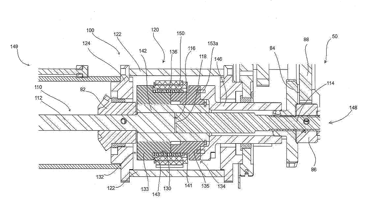
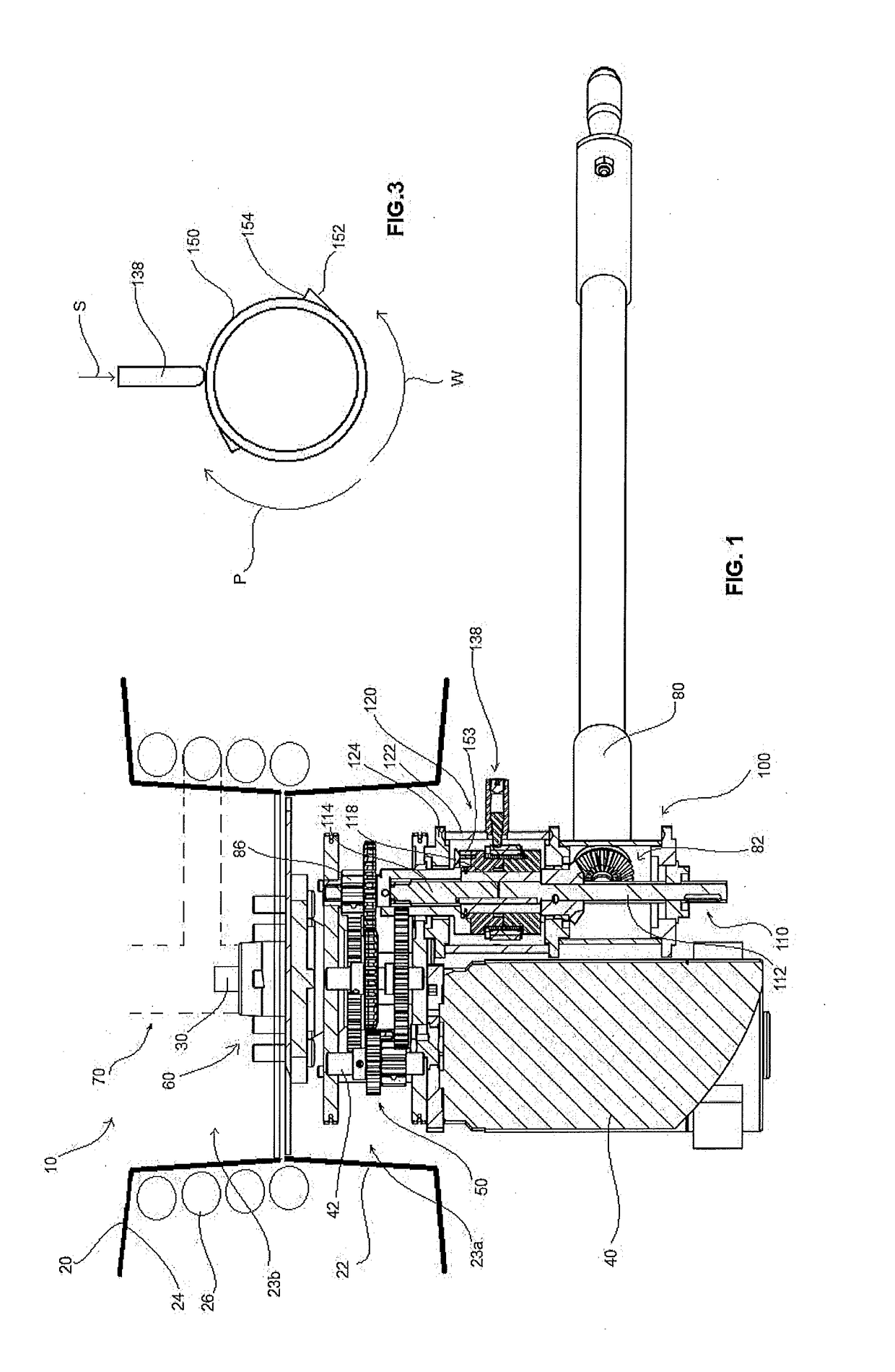
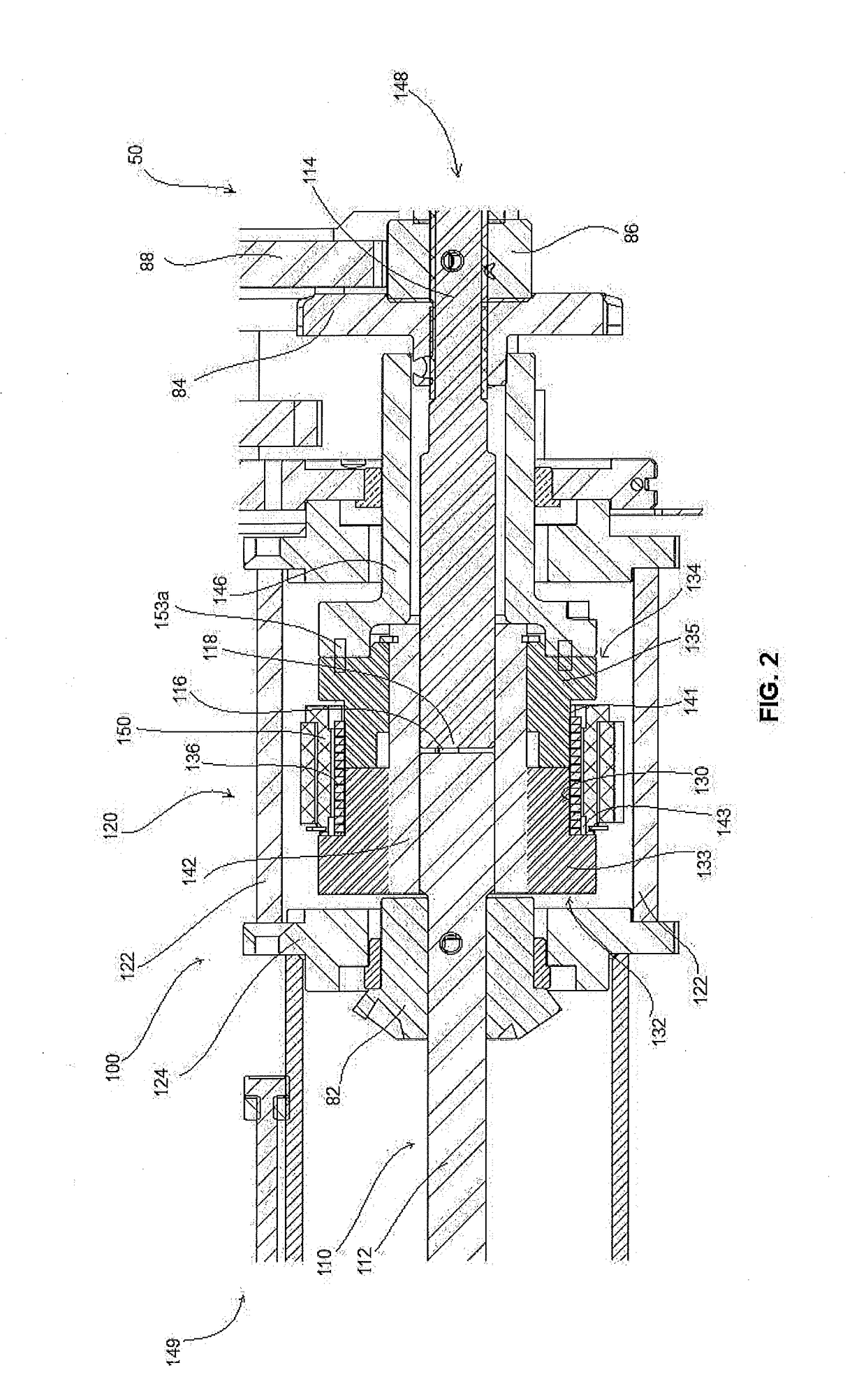
[0019]FIG. 1 depicts a reel assembly 10 comprising a spool 20, a hub shaft 30, an electric motor 40, a gear assembly 50, a reel hub generally referenced 60, a riser assembly 70, a removable manual power takeoff (PTO) 80, and a release assembly 100.

[0020]The spool 20 may be used, for example, for a fire hose or similar and comprises a central core drum 22 defining a pair of central cavities 23a, 23b. The first cavity 23a is adapted to house the gear assembly 50. The second cavity 23b is adapted to house the riser assembly 70. The gear assembly 50 and the riser assembly 70 are mounted either side of the hub 60 in the central cavities 23a, 23b. Hose 26 is wound onto the spool 20 and retained on the core drum 22 by side disc flanges 24.

[0021]The electric motor 40 is preferably an AC electrical motor, suitable for mains usage, but could also be a DC motor, or indeed another form of motor such as a spring motors, or a hydraulic or pneumatic motor. The electric motor is preferably main pow...


PUM


Abstract

A reel assembly (10) having a spool (20) comprising a drum core (22) and side disc flanges (24) attached to the drum core (22) for retaining a wound hose (26) on the spool (20), and a release mechanism (120) operatively engaging the spool (20) via a drive shaft (110). The release mechanism (120) has a pair of rotatable hubs (132, 134) arranged in axial alignment and having a clamping spring (136) fitted around the rotatable hubs (132, 134) and arranged to clamp the hubs (132, 134) together in fixed rotational relation, wherein the clamping spring (136) opens to releases the rotatable hubs (132, 134) when the spool (20) is rotated in a payout direction so that the rotatable hubs (132, 134) disengage and the spool (20) can freewheel.

Description

FIELD OF THE INVENTION[0001]The present invention relates to hose reel assemblies, and in particular a hose reel assembly having an automatic release mechanism.BACKGROUND OF THE INVENTION[0002]Industrial hose reels have various applications, such as in firefighting, and general purpose use in industrial plants. For such industrial reel devices, it is desirable for the reel to wind on a hose under control, yet pay out freely as required. Power-operated devices have been used to supply this functionality by relying upon an electromagnetic clutch mechanism which is activated or deactivated as the case may be by an operator when the hose is to be wound or payed out.[0003]As will be appreciated, such reels are often required to be used to respond to emergencies when time of the essence, and when there are distractions competing for attention. Under such conditions, operators can inadvertently overlook the need to deactivate a drive mechanism to pay out a wound hose for use. Besides delay...

Claims


Application Information

Patent Timeline
Patent Type & Authority Applications(United States)
IPC IPC(8): B65H75/34B65H75/44
CPCB65H75/34B65H75/4463B65H75/4471B65H75/4431A62C33/00B65H75/4428B65H75/4434B65H75/4486B65H2701/33F16D41/206B65H75/38B65H75/30F16D41/02
Inventor MORGAN, SEANMORGAN, STUART
Owner SPRAY NOZZLE ENG
Why Eureka
Try Eureka