Automatically releasable hose reel assembly

a technology of automatic releasable and hose reels, which is applied in the direction of clutches, freewheel clutches, mechanical equipment, etc., can solve the problems of operator injury, electromechanical drive devices tend to be oversized and underpowered, and inadvertently overlooking the need of operators, etc., to reduce the load, reduce the risk, and reduce the effect of friction resistan

Active Publication Date: 2021-03-30
SPRAY NOZZLE ENG
View PDF7 Cites 0 Cited by
  • Summary
  • Abstract
  • Description
  • Claims
  • Application Information

AI Technical Summary

Benefits of technology

[0004]The inventive concept arises from a recognition that a reel assembly can advantageously incorporate a release mechanism that is in effect automatically actuated when a hose wound on the reel is tensioned for payout. Ideally, a reel moreover incorporates such a release mechanism in a simple, robust, compact and mechanical form, which advantageously avoids the use of existing outsized electromechanical clutching devices, which to date have required manual deactivation to achieve release.
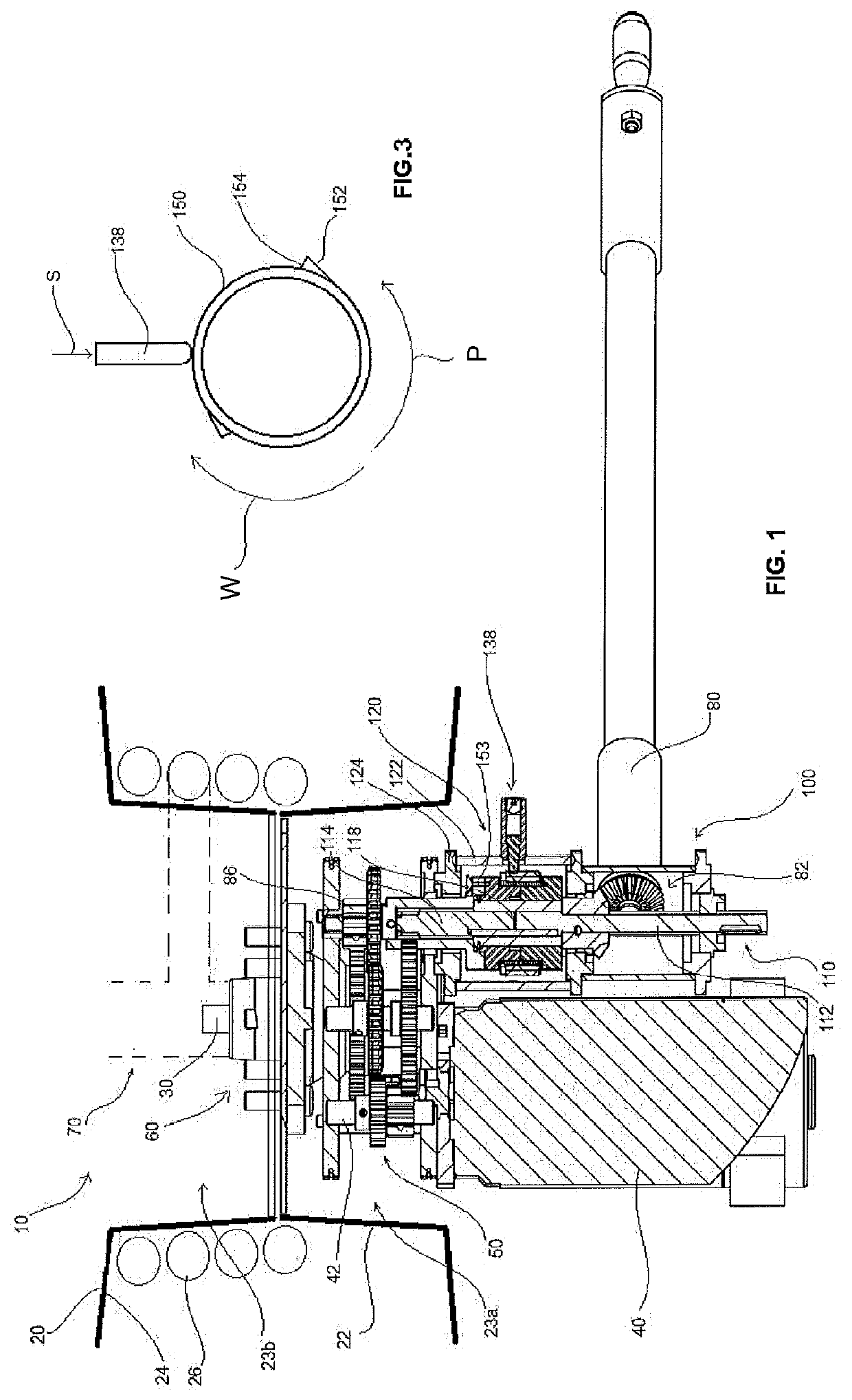
[0007]A cam collar is provided in the form of a cylindrical sleeve having cam ramps that provide a ratcheting function in conjunction with the pawling action of a spring-loaded contact pin that bears against the surface of the cam collar. The ratcheting action of the cam collar and cam ramps co-operating with the loaded contact pin arrests rotation of the cam collar when the spool is being payed out, but permits rotation of the cam collar when the hose is being wound. The cam ramps are angled or graduated against the tangential profile of the cam collar to further tension the contact pin as it passes over the cam ramps. The cam ramps terminate in a stop, which acts to arrest rotation of the cam collar, when the contact pin is bearing against it.
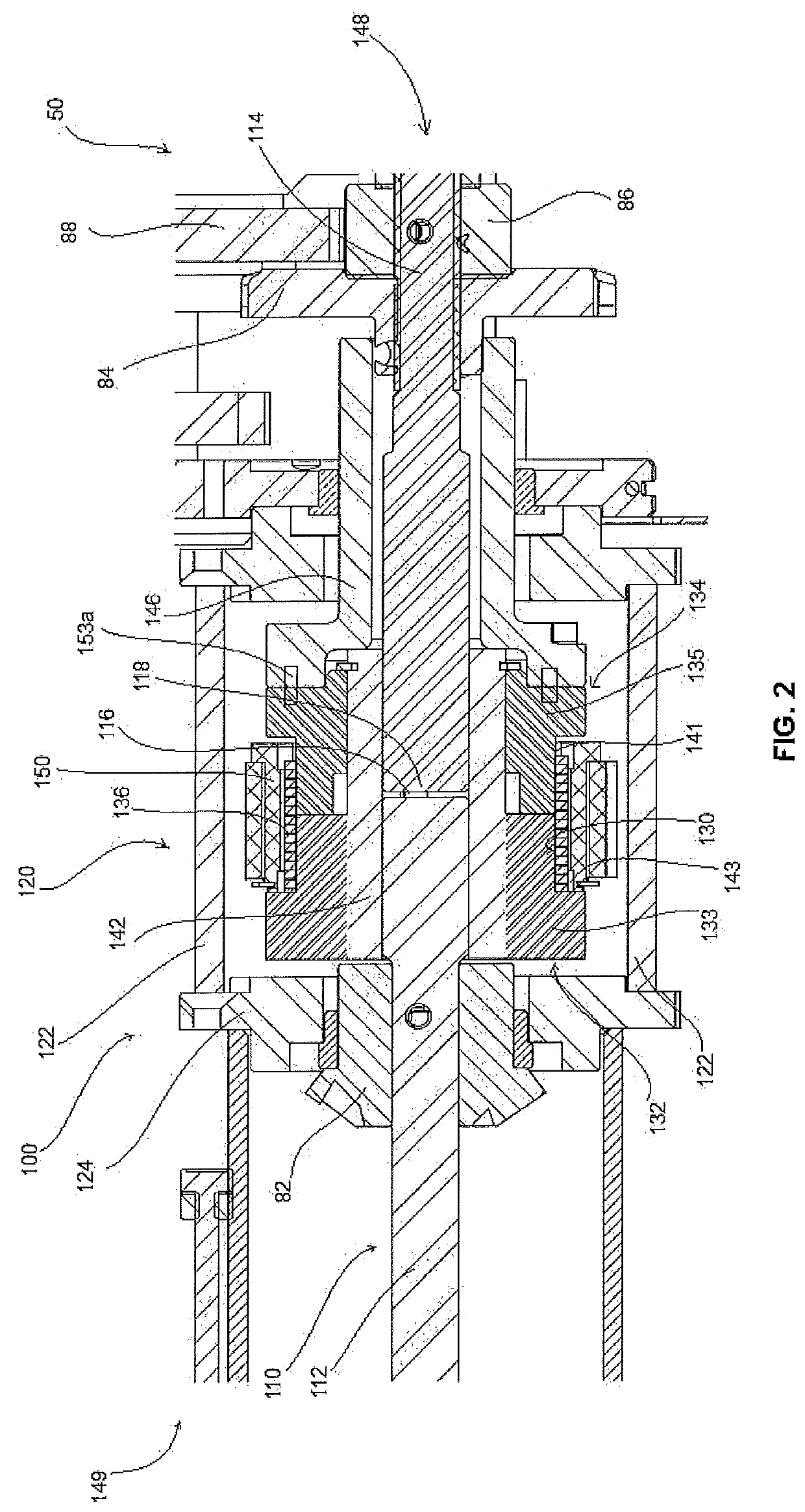
[0008]The ratcheting action of the cam collar and contact pin thus encourages uni-directional rotation of the cam collar in a direction corresponding with the payout direction of the hose, while resisting rotation in the opposite direction, as the stop at the end of the cam ramp presents a locking barrier to rotation owing to interference with the loaded contact pin. The spring has an inside diameter which is slightly smaller than the outside diameter of the input and output hubs. The spring is preferably made from high tensile steel. As the spring is force fit over the input and output hubs, the spring positively engages the hubs. When the drive shaft is torqued for rotation to retract the hose, the spring grips the hubs more tightly and consequently does not slip.
[0010]The first and second parts of the drive shaft are preferably linked by one or more pins that act to align the shafts to minimize relative axial displacement. Together with a sleeve shrouding the drive shaft parts, the pins are effective to make the drive shaft parts co-operate as an integral drive shaft. The advantage of the two drive shaft parts is they permit assembly of the drive shaft from opposed directions and to be advantageously received at their respective abutting ends.
[0014]The release mechanism advantageously operates to permit controlled winding of a hose onto the spool. Typically, a motor is required to wind the (unwound) hose onto the reel, particularly when the hose is extensively paid out. As the hose is wound in, the load is reduced on the motor and there is an elevated risk of the end of the hose dangerously whipping an operator or bystander.
[0015]The release mechanism also permits payout of the item with minimal frictional resistance. Whilst it might be considered desirable to have almost no resistance on payout, in most applications a small amount of frictional resistance avoids unchecked payout. Over-spooling can be avoided by a drag brake, incorporated as an adjunct device separate to the release mechanism.

Problems solved by technology

Under such conditions, operators can inadvertently overlook the need to deactivate a drive mechanism to pay out a wound hose for use.
Besides delay and inconvenience, this can also result in operator injury as a consequence of vigorously pulling on a wound hose in an attempt to get the reel assembly paying out hose, when the hose reel is not yet released.
Moreover, electromechanical drive devices tend to be oversized and underpowered as a consequence of striking an unsatisfactory compromise between the power required to wind a hose at full pay out, and the limited space available in an industrial hose reel assembly.

Method used


Image

  • Automatically releasable hose reel assembly
  • Automatically releasable hose reel assembly

Examples


Embodiment Construction

[0019]FIG. 1 depicts a reel assembly 10 comprising a spool 20, a hub shaft 30, an electric motor 40, a gear assembly 50, a reel hub generally referenced 60, a riser assembly 70, a removable manual power takeoff (PTO) 80, and a release assembly 100.

[0020]The spool 20 may be used, for example, for a fire hose or similar and comprises a central core drum 22 defining a pair of central cavities 23a, 23b. The first cavity 23a is adapted to house the gear assembly 50. The second cavity 23b is adapted to house the riser assembly 70. The gear assembly 50 and the riser assembly 70 are mounted either side of the hub 60 in the central cavities 23a, 23b. Hose 26 is wound onto the spool 20 and retained on the core drum 22 by side disc flanges 24.

[0021]The electric motor 40 is preferably an AC electrical motor, suitable for mains usage, but could also be a DC motor, or indeed another form of motor such as a spring motors, or a hydraulic or pneumatic motor. The electric motor is preferably main pow...


PUM


Abstract

A reel assembly (10) having a spool (20) comprising a drum core (22) and side disc flanges (24) attached to the drum core (22) for retaining a wound hose (26) on the spool (20), and a release mechanism (120) operatively engaging the spool (20) via a drive shaft (110). The release mechanism (120) has a pair of rotatable hubs (132, 134) arranged in axial alignment and having a clamping spring (136) fitted around the rotatable hubs (132, 134) and arranged to clamp the hubs (132, 134) together in fixed rotational relation, wherein the clamping spring (136) opens to releases the rotatable hubs (132, 134) when the spool (20) is rotated in a payout direction so that the rotatable hubs (132, 134) disengage and the spool (20) can freewheel.

Description

FIELD OF THE INVENTION[0001]The present invention relates to hose reel assemblies, and in particular a hose reel assembly having an automatic release mechanism.BACKGROUND OF THE INVENTION[0002]Industrial hose reels have various applications, such as in firefighting, and general purpose use in industrial plants. For such industrial reel devices, it is desirable for the reel to wind on a hose under control, yet pay out freely as required. Power-operated devices have been used to supply this functionality by relying upon an electromagnetic clutch mechanism which is activated or deactivated as the case may be by an operator when the hose is to be wound or payed out.[0003]As will be appreciated, such reels are often required to be used to respond to emergencies when time is of the essence, and when there are distractions competing for attention. Under such conditions, operators can inadvertently overlook the need to deactivate a drive mechanism to pay out a wound hose for use. Besides de...

Claims


Application Information

Patent Timeline
Patent Type & Authority Patents(United States)
IPC IPC(8): B65H75/44B65H75/34F16D41/20A62C33/00F16D41/02B65H75/38B65H75/30
CPCB65H75/34A62C33/00B65H75/4428B65H75/4431B65H75/4434B65H75/4463B65H75/4471B65H75/4486F16D41/02F16D41/206B65H75/30B65H75/38B65H2701/33
Inventor MORGAN, SEANMORGAN, STUART
Owner SPRAY NOZZLE ENG
Why Eureka
Try Eureka