Electrical power supply circuit in an aircraft for electrical equipment including a de-icing circuit

a technology of electrical equipment and de-icing circuit, which is applied in the direction of power installations, electric devices, transportation and packaging, etc., can solve the problems of running the risk of becoming dimension-determining or even prohibitive, and electrical losses that are not negligible, and achieve the effect of reducing the size of the converter

Active Publication Date: 2010-11-11
SAFRAN ELECTRICAL & POWER
View PDF16 Cites 16 Cited by
  • Summary
  • Abstract
  • Description
  • Claims
  • Application Information

AI Technical Summary

Benefits of technology

[0012]The circuit of the invention thus makes it possible to reduce the length of cable for conveying electricity to the de-icing circuit. Furthermore, the cable conveying electricity from the electricity distribution network on board the airplane may be of small diameter. This makes it possible to optimize the weight and the bulk of the cables. In addition, the de-icing circuit does not impose any particular regulation constraints and consequently the power supply generator may be of a configuration that is simple, robust, compact, and light in weight. Furthermore, there is no need to have an electrical resistance to be dedicated solely to dissipating the electricity that can be returned to the DC electricity distribution bus by the electrical actuators in the nacelle. This further reduces weight and enables electricity to be saved.
[0014]The circuit of the invention thus enables the de-icing circuit (which is purely resistive) to receive an alternating voltage without the alternating voltage being transformed into a DC voltage, thus enabling power losses to be reduced and reducing the size and the weight of the circuit.
[0019]The at least one engine control unit (ECU) is advantageously connected to said permanent magnet generator to receive an alternating voltage. This enables the circuit to be simplified.
[0021]According to a feature of the present invention, the power supply generator is a wound-rotor machine and said permanent magnet generator corresponds to a permanent magnet stage of said wound-rotor machine. It is thus possible to save on one outlet shaft from the accessory gearbox.
[0025]The circuit thus makes it possible to have a secure electricity node available in the vicinity of the engine for powering loads integrated in the engine or situated in its vicinity, with only one link to the electricity network on board the aircraft sufficing to ensure that electricity is available on the electricity network of the engine. Furthermore, the converter can be dimensioned for all of the electrical equipment with the exception of the de-icing equipment, thereby reducing the size of the converter.

Problems solved by technology

The delivery of electricity from the network on board the aircraft to the various loads external to the fuselage by means of power supply lines which need to be made very safe and to be insulated lines represent weight and bulk that are considerable, running the risk of becoming dimension-determining or even prohibitive if the amount of equipment to be powered increases, and the delivery itself presents electrical losses that are not negligible.

Method used


Image

  • Electrical power supply circuit in an aircraft for electrical equipment including a de-icing circuit
  • Electrical power supply circuit in an aircraft for electrical equipment including a de-icing circuit
  • Electrical power supply circuit in an aircraft for electrical equipment including a de-icing circuit

Examples


Embodiment Construction

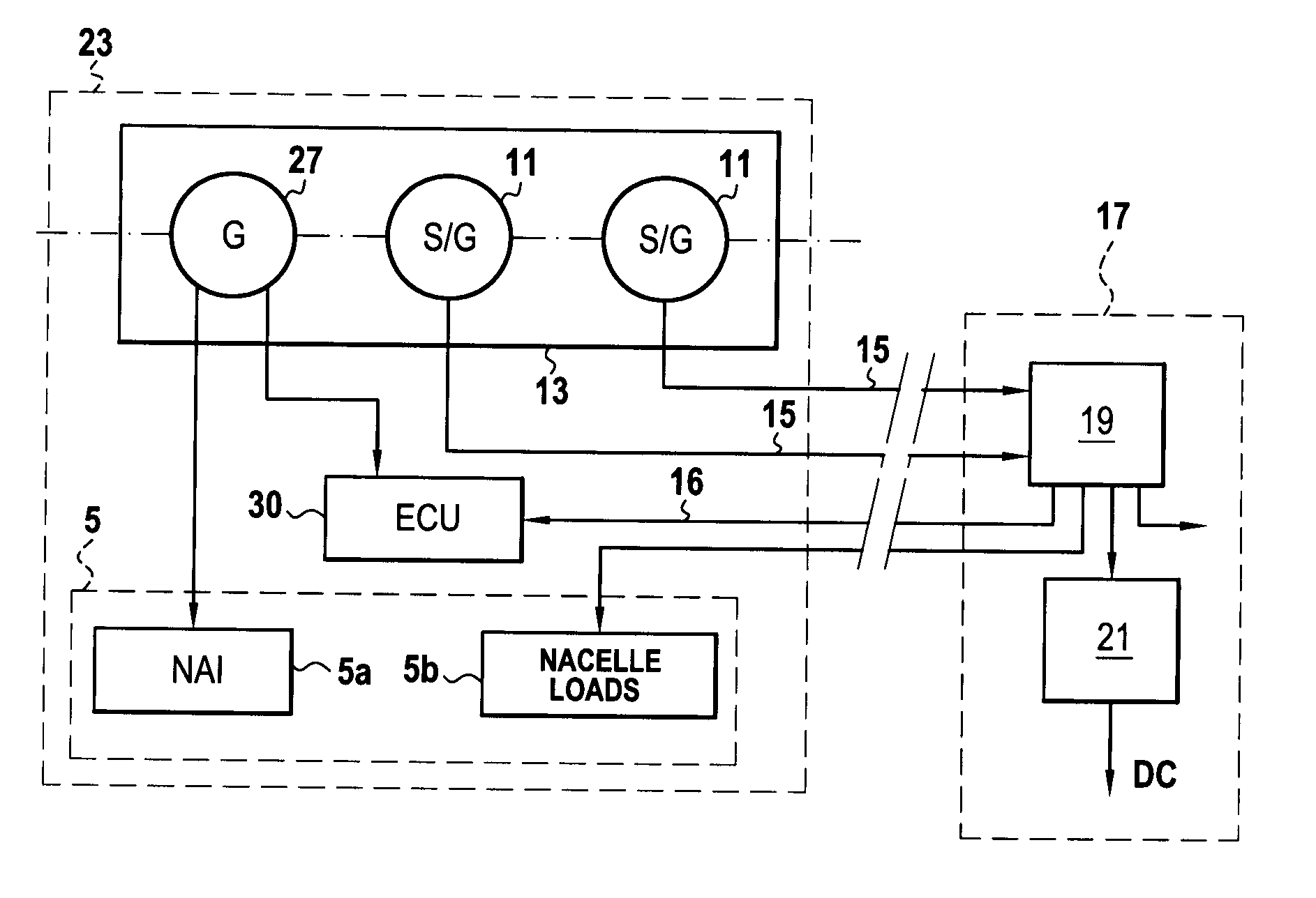
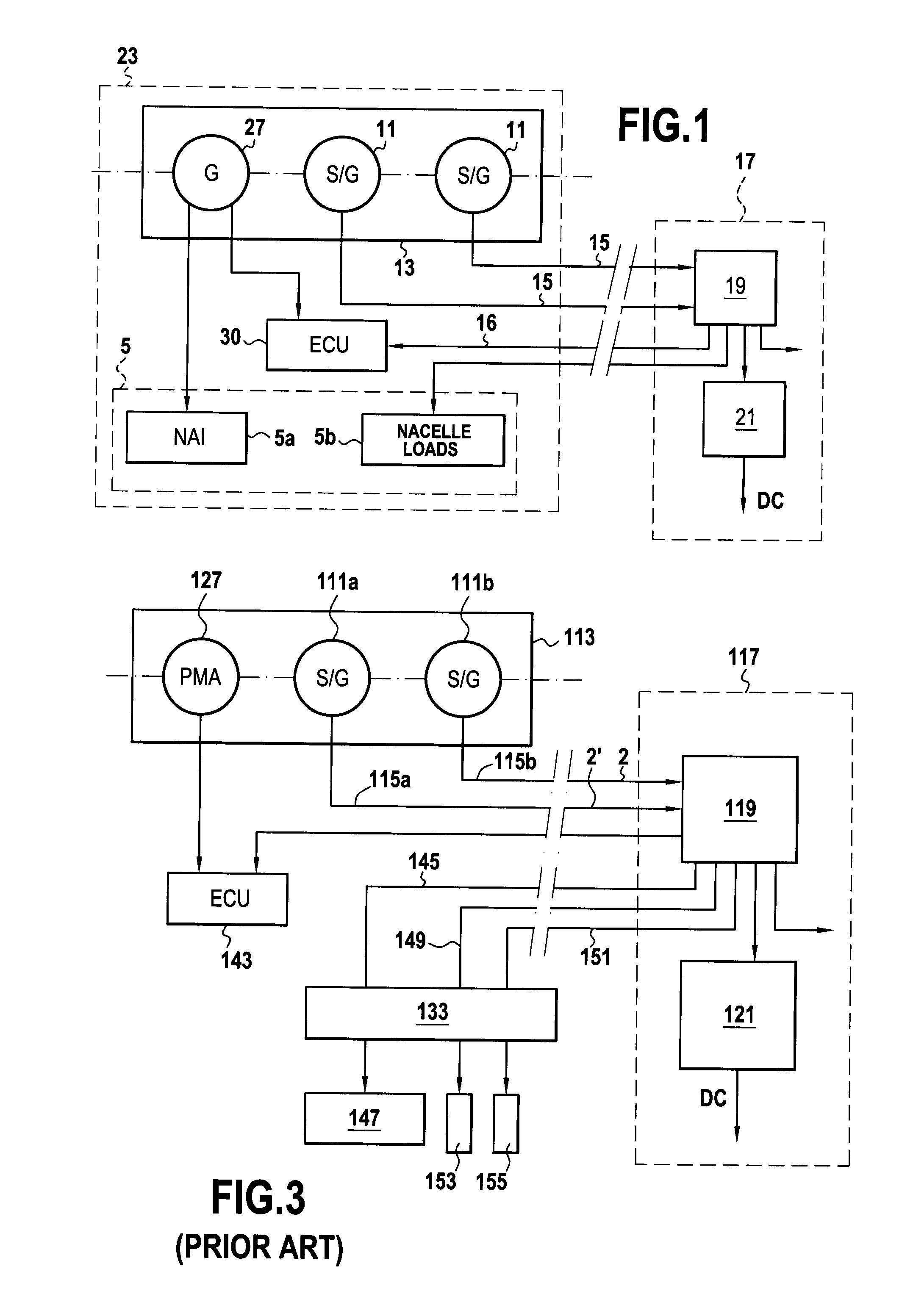
[0031]FIG. 1 is a circuit diagram for electrically powering and controlling a set 5 of pieces of electrical equipment 5a and 5b in an aircraft engine and in its surroundings, in particular in association with a gas turbine airplane engine.

[0032]The circuit of FIG. 1 comprises at least one generator 11 such as an S / G mounted on an accessory gearbox (represented by 13) that is mechanically coupled to a turbine shaft of the engine (not shown). The alternating voltage delivered by the S / G generator(s) 11 is conveyed by one or more lines 15 to an electrical network 17 for distributing electricity on board the airplane, referred to as the “on-board network”. A circuit 19 of the on-board network supplies one or more distribution buses with an alternating voltage that is typically regulated at 115 Vac or 230 Vac and at a frequency that varies as a function of the speed of rotation of the turbine shaft. The circuit 19 may also power a voltage converter circuit 21 for delivering a regulated D...


PUM


Abstract

The invention relates to an electrical power supply circuit in an aircraft, the circuit comprising an electricity distribution network 17 on board the aircraft for powering electrical equipment 5b situated in an engine of the aircraft or in the surroundings of said engine and a power supply generator 27 integrated in the engine of the aircraft for powering a de-icing circuit 5a. The electrical equipment comprises nacelle loads (5b) connected to a DC voltage distribution bus (35), itself being connected to a voltage converter circuit (34) powered by the distribution network (17). The de-icing circuit (5a) comprises at least one electrical resistance (61) for dissipating electricity possibly returned to the DC voltage distribution bus (35) by at least some of the nacelle loads.

Description

BACKGROUND OF THE INVENTION[0001]The invention relates to supplying electricity to electrical equipment in an aircraft engine and / or its surroundings.[0002]The field of application of the invention is more particularly that of airplane engines, in particular gas turbine engines. Nevertheless, the invention is also applicable to helicopter engines.[0003]The term “electrical equipment in an aircraft engine or in its surroundings” is used herein to cover not only electrical equipment that is useful for enabling the engine to operate, but also electrical equipment associated with the engine nacelle, such as, for example, de-icing or anti-icing electrical circuits such as circuits for nacelle anti-icing (NAI) or actuators for use in a thrust-reverse cowl opening system (TRCOS) or electromechanical actuators for use in electrical thrust-reverse actuation control (ETRAC) for a gas turbine airplane engine, or even circuits associated with the wing carrying the engine, such as, for example, ...

Claims


Application Information

Patent Timeline
Patent Type & Authority Applications(United States)
IPC IPC(8): B60L1/00
CPCB64D15/12B64D41/00Y02T50/44B64D2221/00B64D2033/0233Y02T50/40
Inventor BOUDYAF, RACHIDSTUTZ, ANTOINE JEAN-BAPTISTE
Owner SAFRAN ELECTRICAL & POWER
Why Eureka
Try Eureka