
Hydrogen peroxide vapor detoxifying system using honeycomb structure

a technology of hydrogen peroxide and honeycomb, which is applied in the direction of physical/chemical process catalysts, metal/metal-oxide/metal-hydroxide catalysts, and separation processes, etc. it can solve the problems of reducing the efficiency of equipment use, reuse and efficacy of decomposition catalysts, and the patent literature 2 does not consider a method of effectively detoxifying discharged sterilizing solutions, etc., to achieve efficient sucking of hydrogen peroxide vapor

Active Publication Date: 2019-11-05
KOREA INST OF SCI & TECH
View PDF9 Cites 1 Cited by
  • Summary
  • Abstract
  • Description
  • Claims
  • Application Information

AI Technical Summary

Benefits of technology

The patent text describes a need for a system to efficiently break down and detoxify hydrogen peroxide vapor in indoor spaces. The system uses multiple honeycomb structures to absorb and remove the hydrogen peroxide vapor, which is then heated to enhance the decomposition process. The invention also prevents pressure rise and airflow reduction during the suction and discharge of hydrogen peroxide vapor, reducing the burden on equipment.

Problems solved by technology

In general, dilution of mixing hydrogen peroxide vapor with air is the simplest method, but contamination of ambient air with hydrogen peroxide may result in toxicity damage caused by secondary contamination, and thus indoor decomposition and removal is necessary.
Additionally, as shown in FIG. 15, Patent Literature 2 also does not consider a method of effectively detoxifying the discharged sterilizing solution.
So far, decomposition and detoxification of sprayed hydrogen peroxide vapor in a target space includes installing hydrogen peroxide vapor generation equipment inside and performing sterilization and then detoxification, and in this instance, it takes much time to lower the concentration of hydrogen peroxide vapor in the indoor space below the limited concentration, causing problems with reductions in the efficiency of equipment use, and the reuse and efficacy of decomposition catalysts.

Method used


Image

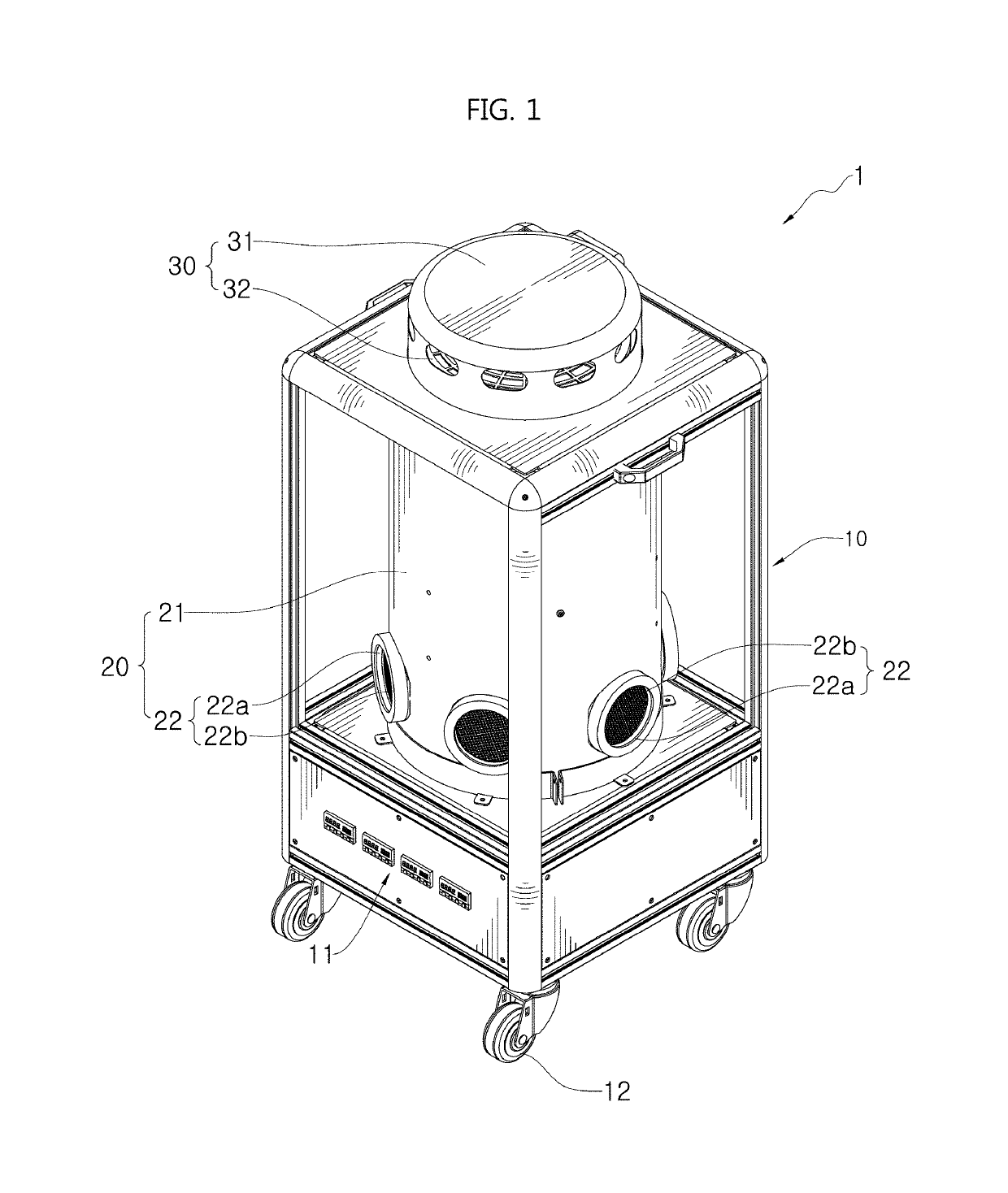
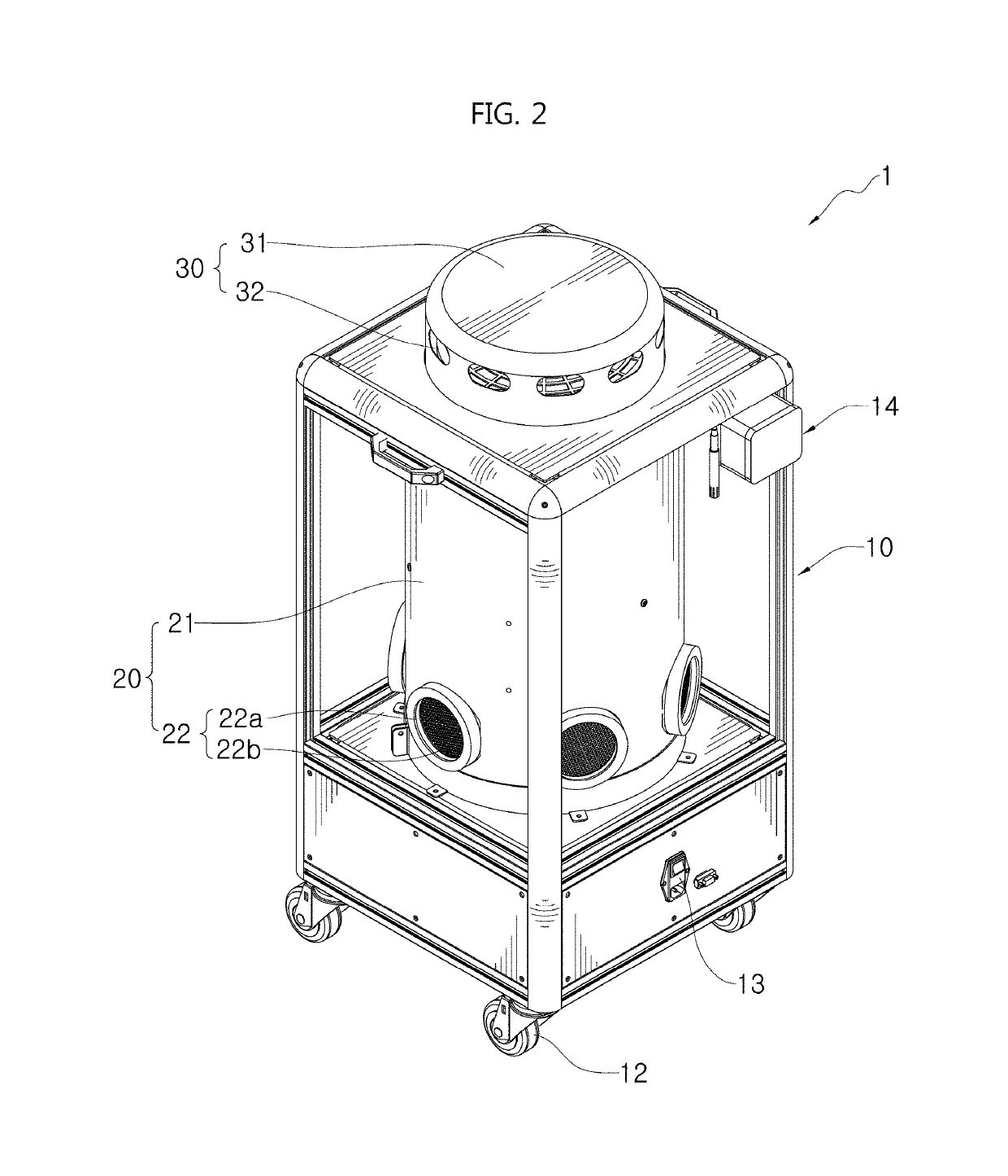
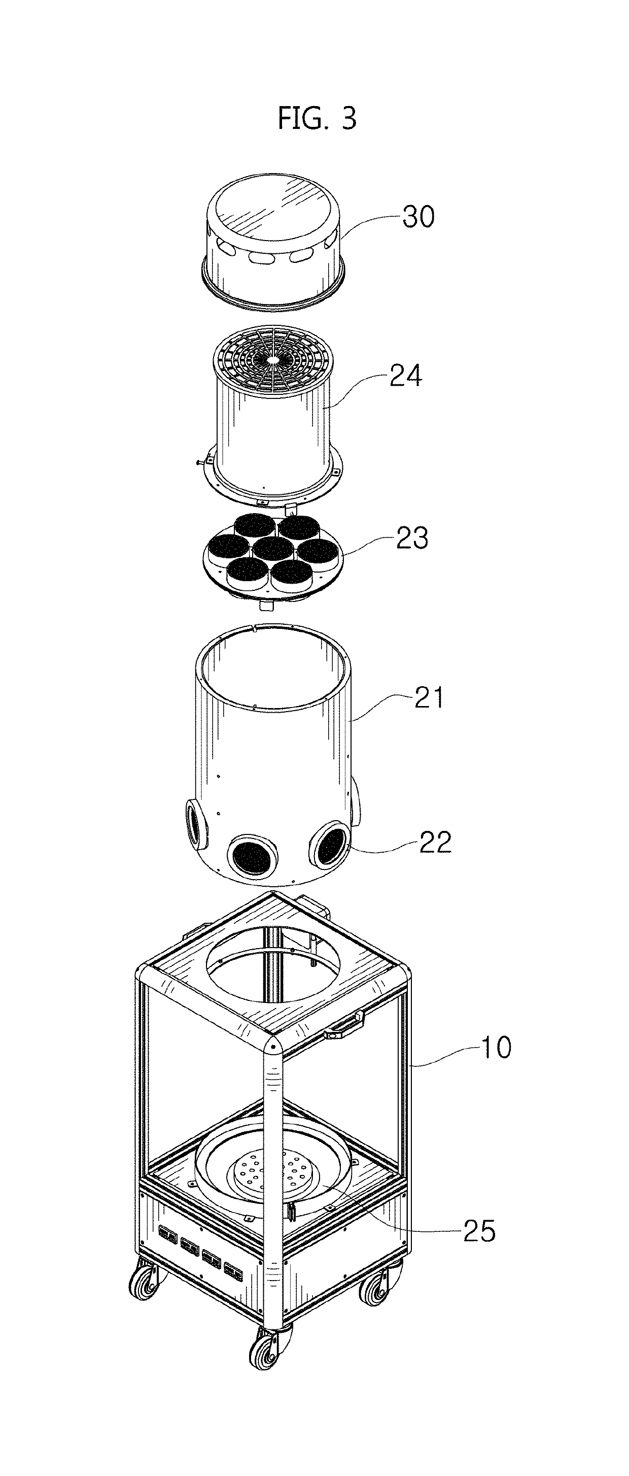
  • Hydrogen peroxide vapor detoxifying system using honeycomb structure
  • Hydrogen peroxide vapor detoxifying system using honeycomb structure
  • Hydrogen peroxide vapor detoxifying system using honeycomb structure

Examples


experiment 1

of Efficiency of Natural Decomposition of Hydrogen Peroxide Vapor

[0084]To test the performance of the vapor decomposition and detoxification system, efficiency of natural decomposition of hydrogen peroxide without using decomposition and detoxification equipment was measured.

[0085]First, to compare the hydrogen peroxide decomposition efficiency of each target according to the objective indication, the experiment conditions were presented as shown in Table 1.

[0086]

TABLE 1Operating time and method of hydrogen peroxidevapor sterilization systemVolume of space to be58.65 m3sterilizedCycle timeConditioning time 7 minsGassing time29 minsDwell time20 minsTotal time56 minsGas injection rate5 g / minAmount of H2O2 usedAbout 150 g

[0087]As shown in Table 1, according to the volume of the sterilization space and the operating time and method of the vapor sterilization apparatus, the concentration of hydrogen peroxide vapor in the target space to be sterilized was maintained at about 250 ppm.

[0088...

experiment 2

oxide Decomposition Efficiency Depending on ON / OFF of the Heating Unit and the Fan Speed of the Exhaust Unit

[0093]To conduct experiment 2, the concentration of hydrogen peroxide vapor in the target space to be sterilized was maintained at about 250 ppm according to the volume of the sterilization space and the operating time and method of the vapor sterilization apparatus as shown in Table 1.

[0094]The hydrogen peroxide decomposition efficiency was measured when the heating unit 25 is ON / OFF, and the result values of FIG. 11 could be obtained.

[0095]A time difference between t1 and t2 found the decomposition efficiency of about 30 min depending on heating or non-heating of the part where hydrogen peroxide vapor is suck.

[0096]Additionally, the hydrogen peroxide decomposition efficiency as a function of the speed of the fan 24a was measured. At the maximum speed corresponding to the fan's maximum air flow of 3,120 m3 / hr and the speed corresponding to its 50%, the hydrogen peroxide vapor...

experiment 3

oxide Decomposition Efficiency of Detoxification System

[0098]The hydrogen peroxide decomposition efficiency of hydrogen peroxide vapor in the target space to be sterilized generated under the condition of the above-described Table 1 was measured using the detoxification system 1 of the present disclosure.

[0099]Maintaining the temperature of the heating plate of the heating unit 25 at 40° C. and the speed of the fan 24a at the maximum fan speed of 100% is avoided to maintain durability and stability of equipment, and during operation, the maximum speed was maintained at 70%.

[0100]Accurate values displayed on the control unit and the display unit were identified, and the hydrogen peroxide decomposition efficiency of the detoxification system of the present disclosure is shown in FIG. 13.

[0101]As shown in FIG. 13, the period of time between the hydrogen peroxide vapor decomposition start t1 after the dwell time and the time t2 at which the hydrogen peroxide concentration is 1 ppm or le...


PUM

PropertyMeasurementUnit
temperatureaaaaaaaaaa
poweraaaaaaaaaa
operating temperatureaaaaaaaaaa

Abstract

The present disclosure relates to a hydrogen peroxide vapor decomposition and detoxification system including a hydrogen peroxide vapor suction unit which sucks hydrogen peroxide vapor in a target space to be sterilized, a hydrogen peroxide vapor decomposition and detoxification unit which decomposes the sucked hydrogen peroxide vapor, a vapor discharge unit which discharges decomposition products of the hydrogen peroxide vapor, and a control unit which controls an amount of vapor suction of the vapor suction unit, decomposition and detoxification of the hydrogen peroxide vapor decomposition and detoxification unit, and the vapor discharge unit.

Description

CROSS-REFERENCE TO RELATED APPLICATION[0001]This application claims priority to Korean Patent Application No. 10-2018-0118938, filed on Oct. 5, 2018, and all the benefits accruing therefrom under 35 U.S.C. § 119, the contents of which in its entirety are herein incorporated by reference.BACKGROUND1. Field[0002]The present disclosure relates to a hydrogen peroxide vapor detoxification system, and more particularly, to a system for hydrogen peroxide decomposition through platinum and palladium catalyst decomposition, by fumigating an indoor or predetermined space contaminated with pathogenic microorganisms or viruses using fumigated hydrogen peroxide, and heating hydrogen peroxide vapor remaining after sterilization to allow it to pass through multi-honeycomb meshwire catalyst cylinders.2. Description of the Related Art[0003]In general, a method for sterilization by generating hydrogen peroxide vapor (HPV) generates active oxygen (oxygen free radical) from hydrogen peroxide molecules,...

Claims


Application Information

Patent Timeline
Patent Type & Authority Patents(United States)
IPC IPC(8): B01D53/86B01D53/76B01D53/96C01B15/013B01J23/44B01J35/04
CPCB01D53/8696B01J23/44B01J35/04C01B15/013B01D53/76B01D53/96B01D2257/93B01D2221/08B01J2523/828B01J23/42B01D53/8671B01D2255/1021B01D2255/1023B01D2255/2092B01D2259/4533B01D2259/4508B01J35/56A61L9/015A61L2/208A61L9/014A61L2202/13A61L2209/211A61L2209/134
Inventor LEE, KANG BONGKIM, YEONG CHEONNAM, YUN SIKJEON, JIN OHPARK, JONG HO
Owner KOREA INST OF SCI & TECH
Learn More