
Rotary bearing

a bearing and rotor technology, applied in the direction of roller bearings, sliding contact bearings, mechanical equipment, etc., can solve the problems of limited area moments of inertia that can be achieved in the bearing race, premature wear occurs in the region, and is subject to high loads. , to achieve the effect of improving support, facilitating production, and reducing the number of bearings

Active Publication Date: 2019-10-22
LIEBHERR COMPONENTS BIBERACH GMBH
View PDF13 Cites 3 Cited by
  • Summary
  • Abstract
  • Description
  • Claims
  • Application Information

AI Technical Summary

Benefits of technology

The patent proposes a design for a bearing assembly that includes both rolling and sliding bearings to achieve a smooth start-up and precise absorption of force components during standstill and rotary operation. By combining these bearings, the assembly can be adapted to various installation situations and can be designed for a compact design. The use of narrow tracks for the axial bearings allows for better support and reduced deformation, and the offset of the tracks results in improved stability and load distribution. The technical effects of the patent include improved load absorption, reduced space requirements, and improved stability and load distribution.

Problems solved by technology

In large ring bearings for special purposes, significant bending moments and tilting forces sometimes act upon the bearing rings, and this can lead to deformation and an angular offset to the bearing races relative to each other, and so premature wear occurs in the region of the bearing races and rolling elements.
Due to a lack of space, the bearing rings of an open-center slewing bearing such as this cannot be manufactured in any desired size, especially in the radial direction, and so the area moments of inertia that can be achieved in the bearing races are limited.
Added to this are the very specific load characteristics associated with this kind of large ring bearings, which in typical applications, such as crane tower or crane mast bearings or rotor blade bearings for adjusting the pitch angle of the rotor blades of wind turbines, remain stationary for a large portion of their operating and service lives, but which are nevertheless subjected to high loads.
In light of the large proportion of downtime and yet high loads, it is not entirely simple to prevent fatigue-related deformations and surface damage to the tracks and rolling elements in the long term and to ensure that they start up and rotate smoothly from a standstill, especially since the rotational speeds are quite low.
However, space problems can arise in this type of cylindrical roller bearings with quite large cylinder diameters, since cylindrical roller bearing of this kind require a lot of installation space.
On the other hand, such wide cylindrical roller bearings react critically to tilting and / or inclinations of the tracks relative to each other, since very quickly only a very small part of the cylindrical rollers actually bears a load.
However, increasing the number of bearing assemblies can result in a larger construction volume, since not only do the rolling bearings require air perpendicular to the rotary axis of the rolling element, but the rotary axes should be distanced from each other in the direction of the rolling elements, as well, if multiple rolling bearings are arranged next to each other on one side of the lug ring.
In confined installation conditions, this can cause problems, at least when the lug ring and / or the ring sections of the grooved ring supported on it are not thinned out too much, which would nullify the increase in tilting and torsional rigidity achieved by the larger number of bearing assemblies.
Additionally, two such offset and relatively narrow tracks in the sum bring about a longer line contact between the rolling elements and tracks or between the sliding block and track, in particular also when slight inclinations of the tracks occur as a result of deformations.

Method used


Image

  • Rotary bearing
  • Rotary bearing

Examples


Embodiment Construction

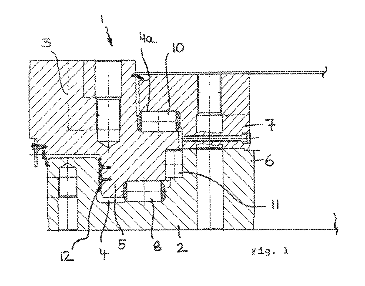
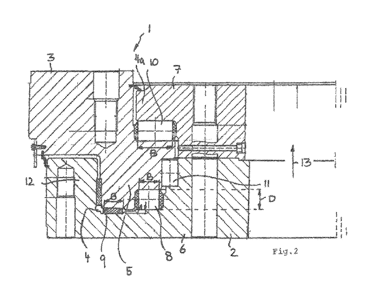
[0028]As FIGS. 1 and 2 show, the rolling bearing 1 can comprise two bearing races 2 and 3, of which one bearing race 2 forms an inner ring and the other bearing race 3 forms an outer ring. Said inner ring 2 can have a smaller inner diameter than the outer ring 3 and / or the outer ring 3 can have a larger outer diameter than the inner ring 2.

[0029]The one bearing race 2, preferably the inner ring, can have a groove 4 which is open toward the other bearing race 3, preferably toward the outer ring, and into which the other bearing race 3 engages with a lug ring 5 that is provided thereon so as to form a gap and / or with spacing on all sides. This groove 4 can advantageously encompass the lug ring 5 from four sides, namely on two opposing sides of the lateral surface and on two opposing sides of the front side of the lug ring 5.

[0030]Here, said groove 4 has a—roughly—U-shaped bottom contour in which the groove bottom—right and left in FIG. 1—is encompassed by two bearing ring limbs. Furth...


PUM


Abstract

A rotary bearing, in particular a large open-centered ring bearing, having two concentric bearing races, of which one bearing race has a groove which is open toward the other bearing race, and the other bearing race has a lug ring that engages in the aforementioned groove. The lug ring can be supported against the groove in the axial and radial directions of the rotary bearing with a plurality of bearing assemblies that include at least two axial bearings mounted on opposite lug ring end faces, and at least one radial bearing that is mounted on an outer surface of the lug ring. The plurality of bearing assemblies have at least one sliding bearing and at least one rolling bearing situated between the lug ring and the groove.

Description

CROSS-REFERENCE TO RELATED APPLICATIONS[0001]The present application is a continuation of International Application No. PCT / EP2016 / 001293, filed Jul. 26, 2016, which claims priority to German Utility Model Application No. 20 2015 006 588.0, filed Sep. 18, 2015, both of which are incorporated by reference herein in their entireties.BACKGROUND1) Technical Field[0002]The present invention relates to a rotary bearing, in particular a large open-centered ring bearing, comprising two concentric bearing races, of which one bearing race has a groove which is open toward the other bearing race, and the other bearing race has a lug ring that engages in the aforementioned groove, wherein the lug ring is supported against the groove in the axial and radial directions of the rotary bearing by means of a plurality of bearing assemblies that comprise at least two axial bearings mounted on opposite lug ring end faces, and at least one radial bearing that is mounted on an outer surface of the lug ri...

Claims


Application Information

Patent Timeline
IPC IPC(8): F16C17/02F16C19/38F16C33/60F16C33/58F16C21/00F16C17/10
CPCF16C19/381F16C17/02F16C33/60F16C21/00F16C17/10F16C33/585F16C2300/14F16C2240/70
Inventor SAUTER, HERBERT
Owner LIEBHERR COMPONENTS BIBERACH GMBH
Learn More