Method of cam phase control based on cylinder wall temperature

a technology of camshaft and camshaft, which is applied in the direction of electric control, valve drive, machine/engine, etc., can solve the problems of more restrictive restrictions on the cold operation of the internal combustion engin

Inactive Publication Date: 2019-10-08
GM GLOBAL TECH OPERATIONS LLC
View PDF6 Cites 0 Cited by
  • Summary
  • Abstract
  • Description
  • Claims
  • Application Information

AI Technical Summary

Benefits of technology

[0002]Internal combustion engines combust an air and fuel mixture within cylinders to drive pistons, which produces drive torque. Air flow into the engine is regulated via a throttle. More specifically, the throttle adjusts throttle area, which increases or decreases air flow into the engine. As the throttle area increases, the air flow into the engine increases. A fuel control system adjusts the rate that fuel is injected to provide a desired air / fuel mixture to the cylinders and / or to achieve a desired torque output. Increasing the amount of air and fuel provided to the cylinders increases the torque output of the engine.
[0003]In many internal combustion engines, variable valve timing or phasing of the intake and exhaust valves with the use of cam phasing of an internal combustion engine is utilized as a control method which provides improved engine performance including enhanced power and torque, increased fuel efficiency and reduced emissions. Depending upon engineering goals and other criteria, variable valve phasing may include the phasing of the opening and closing of the intake valve, opening and closing of the exhaust valve, lift of the intake and exhaust valves, and combinations thereof.

Problems solved by technology

The constraints for the cold operation of the internal combustion engine are more restrictive than the constraints for the warm operation of the internal combustion engine.

Method used


Image

  • Method of cam phase control based on cylinder wall temperature
  • Method of cam phase control based on cylinder wall temperature
  • Method of cam phase control based on cylinder wall temperature

Examples


Embodiment Construction

[0032]The following description is merely exemplary in nature and is not intended to limit the present disclosure, application, or uses.

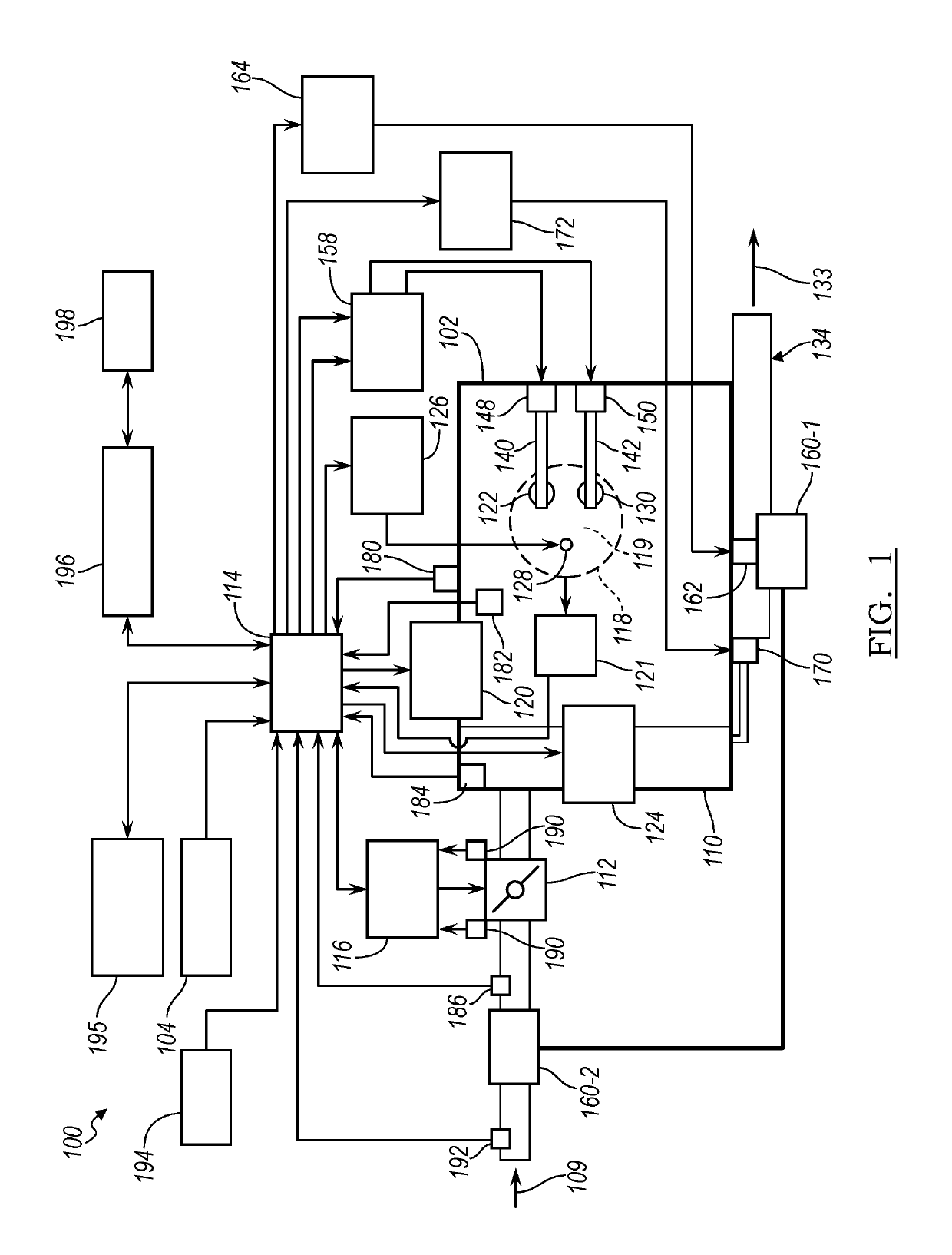
[0033]An engine control module (ECM) controls torque output of an engine. More specifically, the ECM controls actuators of the engine based on target values, respectively, based on a requested amount of torque. For example, the ECM controls intake and exhaust camshaft phasing based on target intake and exhaust phaser angles, a throttle valve based on a target throttle opening, an exhaust gas recirculation (EGR) valve based on a target EGR opening, and a wastegate of a turbocharger based on a target wastegate duty cycle.

[0034]Referring now to FIG. 1, a functional block diagram of an exemplary engine system 100 is presented. The engine system 100 includes a spark ignition internal combustion engine 102 that combusts an air / fuel mixture to produce drive torque for a vehicle based on driver input from a driver input module 104.

[0035]Air 109 is drawn int...


PUM


Abstract

A method of controlling intake and exhaust cam phase in an internal combustion engine includes sensing an engine speed and an engine load of the internal combustion engine, sensing or estimating a wall temperature of a cylinder of the internal combustion engine, utilizing the engine speed and the engine load in one or more lookup tables based on the cylinder wall temperature to determine intake phaser constraint values and exhaust phaser constraint values for cold operation of the internal combustion engine, and transitioning the intake phaser constraint values and the exhaust phaser constraint values for cold operation to intake phaser constraint values and exhaust phaser constraint values based on one or more lookup tables for normal hot operation of the internal combustion engine.

Description

INTRODUCTION[0001]The present disclosure relates to camshaft phase control. More specifically, the present disclosure relates to a method of controlling camshaft phase in an internal combustion engine based on cylinder wall temperature of the internal combustion engine.[0002]Internal combustion engines combust an air and fuel mixture within cylinders to drive pistons, which produces drive torque. Air flow into the engine is regulated via a throttle. More specifically, the throttle adjusts throttle area, which increases or decreases air flow into the engine. As the throttle area increases, the air flow into the engine increases. A fuel control system adjusts the rate that fuel is injected to provide a desired air / fuel mixture to the cylinders and / or to achieve a desired torque output. Increasing the amount of air and fuel provided to the cylinders increases the torque output of the engine.[0003]In many internal combustion engines, variable valve timing or phasing of the intake and ex...

Claims


Application Information

Patent Timeline
Patent Type & Authority Patents(United States)
IPC IPC(8): F01L1/04F01L1/34F02M26/04F02D41/06F02D13/02F02D41/00F02D41/24
CPCF02D41/2422F02D41/064F02D41/0007F02D41/005F01L1/34F01L1/04F02D13/0219F02D41/2409F02M26/04F02D2250/18F02D2200/101F01L2800/02F02D2013/0292F02D2041/0017F01L2800/00F02D13/0203F02D2041/002F02D2041/001F02D2200/021F02D41/1406F02D2041/1412F02D2041/1433Y02T10/12Y02T10/40
Inventor LEVIJOKI, STEPHEN P.HAYDEN, DAVID N.WHITNEY, CHRISTOPHER E.
Owner GM GLOBAL TECH OPERATIONS LLC
Why Eureka
Try Eureka