Method to select optimal mode on a multi-mode engine with charging

a multi-mode, engine technology, applied in the direction of electric control, combustion engines, machines/engines, etc., can solve the problems of not accurately controlling the engine output torque as desired, traditional engine control systems that do not provide a rapid response to control signals, and traditional engine control systems that do not coordinate engine torque control

Active Publication Date: 2019-07-30
GM GLOBAL TECH OPERATIONS LLC
View PDF2 Cites 0 Cited by
  • Summary
  • Abstract
  • Description
  • Claims
  • Application Information

AI Technical Summary

Benefits of technology

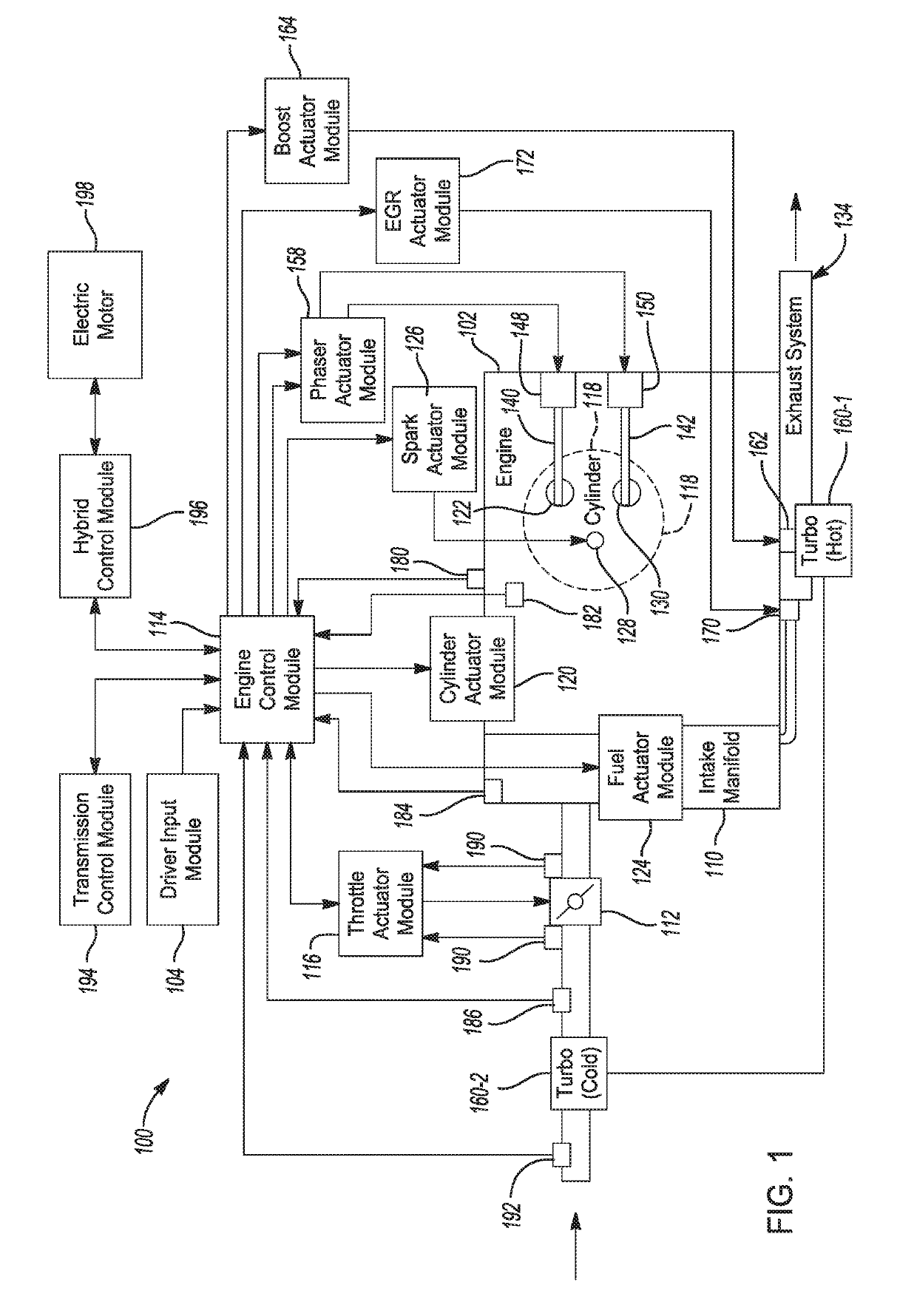
[0002]Internal combustion engines combust an air and fuel mixture within cylinders to drive pistons, which produces drive torque. Air flow into the engine is regulated via a throttle. More specifically, the throttle adjusts throttle area, which increases or decreases air flow into the engine. As the throttle area increases, the air flow into the engine increases. A fuel control system adjusts the rate that fuel is injected to provide a desired air / fuel mixture to the cylinders and / or to achieve a desired torque output. Increasing the amount of air and fuel provided to the cylinders increases the torque output of the engine.

Problems solved by technology

Traditional engine control systems, however, do not control the engine output torque as accurately as desired.
Further, traditional engine control systems do not provide a rapid response to control signals or coordinate engine torque control among various devices that affect the engine output torque, in particular with respect to boosted engines and engines having multiple operating modes.

Method used


Image

  • Method to select optimal mode on a multi-mode engine with charging
  • Method to select optimal mode on a multi-mode engine with charging
  • Method to select optimal mode on a multi-mode engine with charging

Examples


Embodiment Construction

[0032]The following description is merely exemplary in nature and is not intended to limit the present disclosure, application, or uses. For purposes of clarity, the same reference numbers will be used in the drawings to identify similar elements. As used herein, the phrase at least one of A, B, and C should be construed to mean a logical (A or B or C), using a non-exclusive logical “or”. It should be understood that steps within a method may be executed in different order without altering the principles of the present disclosure.

[0033]As used herein, the term module may refer to, be part of, or include an Application Specific Integrated Circuit (ASIC); an electronic circuit; a combinational logic circuit; a field programmable gate array (FPGA); a processor (shared, dedicated, or group) that executes code; other suitable components that provide the described functionality; or a combination of some or all of the above, such as in a system-on-chip. The term module may include memory (...


PUM


Abstract

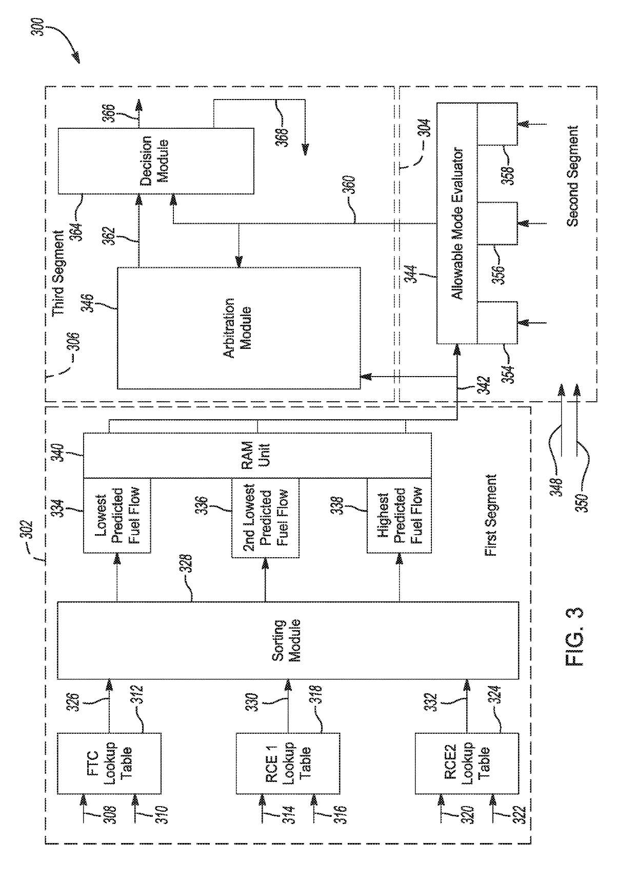
A control method for selecting an optimal multiple step operating mode for a multiple cylinder motor vehicle engine system having variable lift includes prioritizing each of a full torque capacity (FTC) mode having all cylinders operating at high lift, a first reduced capacity economy mode (RCE1) having all cylinders operating at low lift, and a second reduced capacity economy mode (RCE2) having fewer than all of the cylinders operating at low lift with at least one cylinder deactivated based on predicted fuel economy of each of the modes. Multiple constraints are applied to each of the prioritized modes including incorporating boost as one of the constraints by calculating a maximum torque capacity for each mode that is a function of a current boost pressure. A mode determination arbitration is conducted to identify if a change in mode is required.

Description

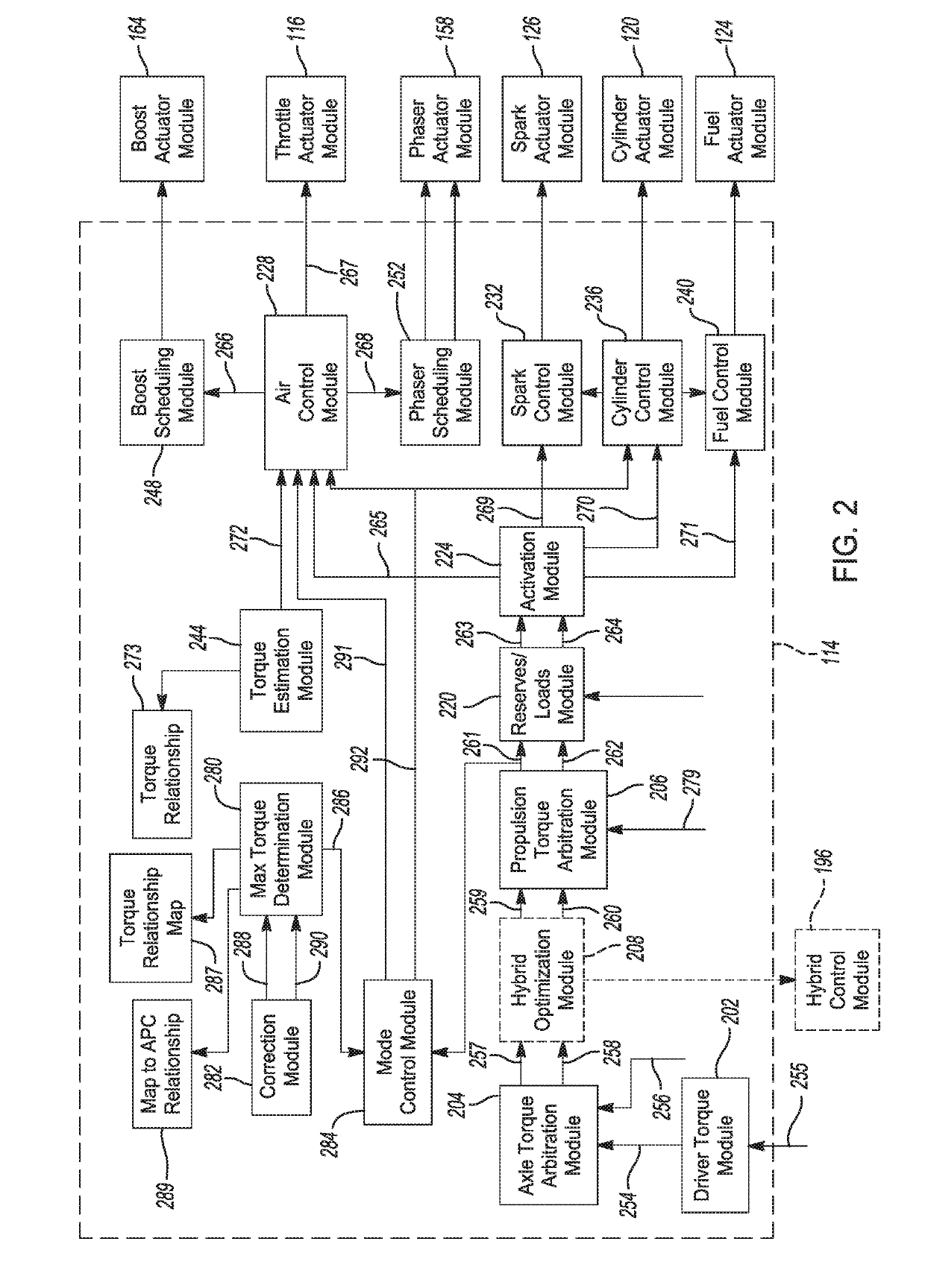
INTRODUCTION[0001]The present disclosure relates to internal combustion engines and more particularly to systems and methods to select a best operating mode for engine operation.[0002]Internal combustion engines combust an air and fuel mixture within cylinders to drive pistons, which produces drive torque. Air flow into the engine is regulated via a throttle. More specifically, the throttle adjusts throttle area, which increases or decreases air flow into the engine. As the throttle area increases, the air flow into the engine increases. A fuel control system adjusts the rate that fuel is injected to provide a desired air / fuel mixture to the cylinders and / or to achieve a desired torque output. Increasing the amount of air and fuel provided to the cylinders increases the torque output of the engine.[0003]In spark-ignition engines, spark initiates combustion of an air / fuel mixture provided to the cylinders. In compression-ignition engines, compression in the cylinders combusts the air...

Claims


Application Information

Patent Timeline
Patent Type & Authority Patents(United States)
IPC IPC(8): F02D41/00F02D41/14
CPCF02D41/0087F02D41/0002F02D41/1406F02D2041/001Y02T10/42F02D2041/1432F02D2200/0625F02D2250/21F02D2041/1412F02D9/10F02D17/02F02D41/3017F02D45/00F02D2200/1002F02D2200/101F02D2200/501F02D2200/606F02D2200/602Y02T10/40
Inventor HAYDEN, DAVID N.DEFFENBAUGH, MICHAELWHITNEY, CHRISTOPHER E.
Owner GM GLOBAL TECH OPERATIONS LLC
Why Eureka
Try Eureka