Secondary Throttle Control Systems and Methods

a throttle valve and control system technology, applied in the direction of electric control, machines/engines, output power, etc., can solve the problems of not providing not accurately controlling the engine output torque, and traditional engine control systems that do not provide a rapid response to control signals, etc., to minimize the noise and vibration of the engine, minimizing the fuel consumption of the engine, and minimizing the effect of exhaust emissions

Active Publication Date: 2022-02-03
GM GLOBAL TECH OPERATIONS LLC
View PDF93 Cites 0 Cited by
  • Summary
  • Abstract
  • Description
  • Claims
  • Application Information

AI Technical Summary

Benefits of technology

[0015]In further features, an MPC module is configured to perform the model predictive control and control engine actuators including the first and second throttle valves based on at least one of (a) minimizi

Problems solved by technology

Traditional engine control systems, however, do not control the engine output torque as accurately as desired.
Further, traditional engine control syst

Method used


Image

  • Secondary Throttle Control Systems and Methods
  • Secondary Throttle Control Systems and Methods
  • Secondary Throttle Control Systems and Methods

Examples


Embodiment Construction

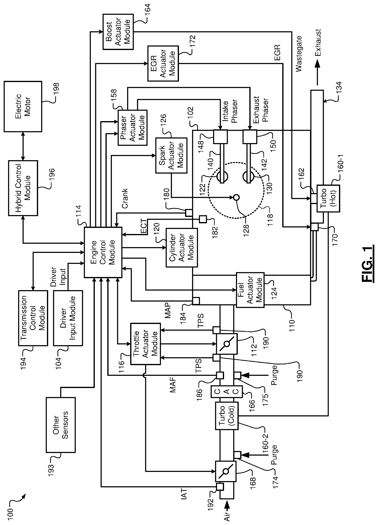
[0032]Some types of boosted engines include a turbocharger that increases airflow into the engine. Boosted engines may include an electric purge pump that pumps fuel vapor from a fuel tank to the intake system. A charge air cooler may cool the air output from the turbocharger compressor before the air flows into the engine for combustion. A first throttle valve is disposed downstream of the turbocharger compressor. An engine control module controls opening of the first throttle valve, for example, based on an engine torque request.

[0033]According to the present disclosure, a second throttle valve is disposed upstream of the turbocharger compressor. The engine control module may generally maintain the second throttle valve fully open to minimize losses. The engine control module, however, at least partially closes the second throttle valve under one or more operating conditions.

[0034]For example, the engine control module may at least partially close the second throttle valve to crea...


PUM


Abstract

An engine system includes: a first throttle valve; a turbocharger compressor disposed downstream of the first throttle valve; a charge air cooler disposed downstream of the turbocharger compressor; a second throttle valve located downstream of the turbocharger compressor; a purge inlet located downstream of the first throttle valve and configured to introduce fuel vapor from a fuel tank into intake air; and an engine control module configured to: maintain the first throttle valve in a fully open position; and selectively close the first throttle valve relative to the fully open position in response to receipt of a request to at least one of: purge fuel vapor from the fuel tank; and at least one of decrease and prevent icing of the charge air cooler.

Description

INTRODUCTION[0001]The information provided in this section is for the purpose of generally presenting the context of the disclosure. Work of the presently named inventors, to the extent it is described in this section, as well as aspects of the description that may not otherwise qualify as prior art at the time of filing, are neither expressly nor impliedly admitted as prior art against the present disclosure.[0002]The present disclosure relates to internal combustion engines, and more specifically, to systems and methods for controlling a throttle valve upstream of a turbocharger compressor.[0003]Internal combustion engines combust an air and fuel mixture within cylinders to drive pistons, which produces drive torque. Air flow into the engine is regulated via a throttle. More specifically, the throttle adjusts throttle area, which increases or decreases air flow into the engine. As the throttle area increases, the air flow into the engine increases. A fuel control system adjusts th...

Claims


Application Information

Patent Timeline
IPC IPC(8): F02D41/00F02D13/02
CPCF02D41/0007F02D2041/002F02D2041/001F02D13/0223F02D41/003F02D41/0235F02D41/123F02D41/0047F02D2200/1002F02D2041/0017F02D2041/1412F02D2041/1433F02D41/1406F02D13/0207F02D41/024F02D2009/0272F02D41/0065F02B29/04F02M25/08F02M26/05Y02T10/12
Inventor RAFTOPOULOS, ANDREW A.SMITH, MICHAEL A.WHITNEY, CHRISTOPHER E.PICOT, NATHAN M.SLEPICKA, CRAIG E.GALLON, ROBERTBURLEIGH, DARRELL W.RAMAPPAN, VIJAY A.
Owner GM GLOBAL TECH OPERATIONS LLC
Why Eureka
Try Eureka