Electronic throttle control using model predictive control

a technology of predictive control and electronic throttle body, applied in the direction of electric control, adaptive control, instruments, etc., can solve the problems of airflow and torque oscillation in the engine, different areas cannot currently be optimally tuned by one pid controller, and traditional electronic throttle control systems do not control the throttle position as accurately as desired

Active Publication Date: 2019-05-14
GM GLOBAL TECH OPERATIONS LLC
View PDF22 Cites 2 Cited by
  • Summary
  • Abstract
  • Description
  • Claims
  • Application Information

AI Technical Summary

Benefits of technology

[0002]Internal combustion engines combust an air and fuel mixture within cylinders to drive pistons, which produces drive torque. Air flow into the engine is regulated via a throttle. The throttle adjusts a throttle area, which increases or decreases air flow into the engine. As the throttle area increases, the air flow into the engine increases. A fuel control system adjusts the rate that fuel is injected to provide a desired air / fuel mixture to the cylinders and / or to achieve a desired torque output. Increasing the amount of air and fuel provided to the cylinders increases the torque output of the engine.
[0020]In another aspect of the present disclosure, the method includes setting at least one constraint for at least one of the throttle motor duty cycle values; and selecting one of multiple future control actions having a lowest cost which satisfies the at least one constraint.

Problems solved by technology

These different areas cannot currently be optimally tuned by one PID controller.
This can result in valve oscillations which can cause airflow and torque oscillations in the engine.
Traditional electronic throttle control systems therefore do not control the throttle position as accurately as desired, and do not provide a rapid response to control signals.

Method used


Image

  • Electronic throttle control using model predictive control
  • Electronic throttle control using model predictive control
  • Electronic throttle control using model predictive control

Examples


Embodiment Construction

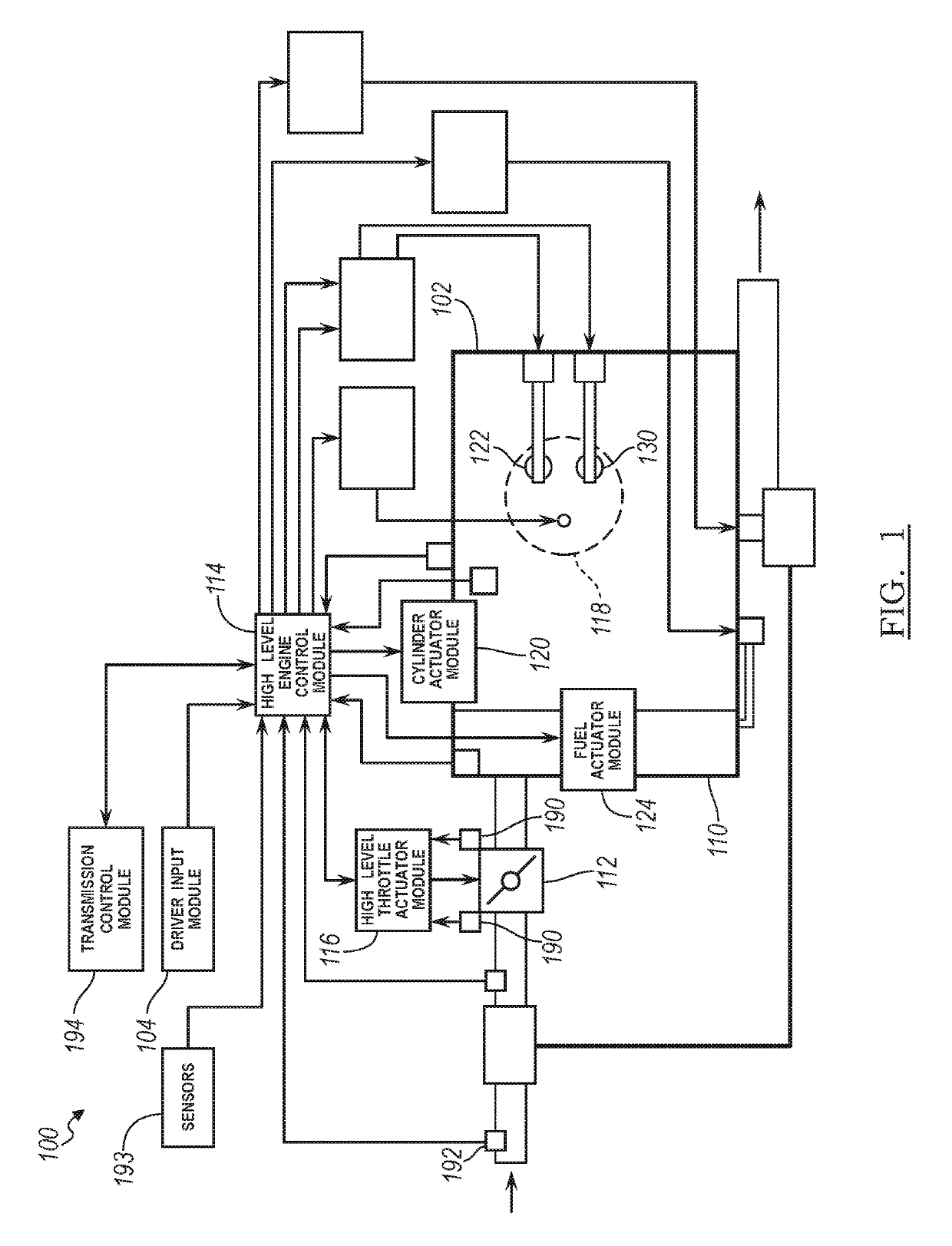
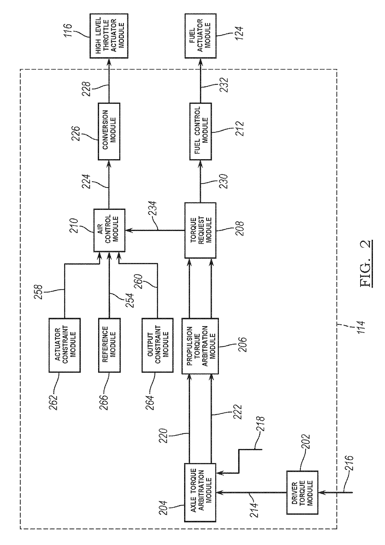
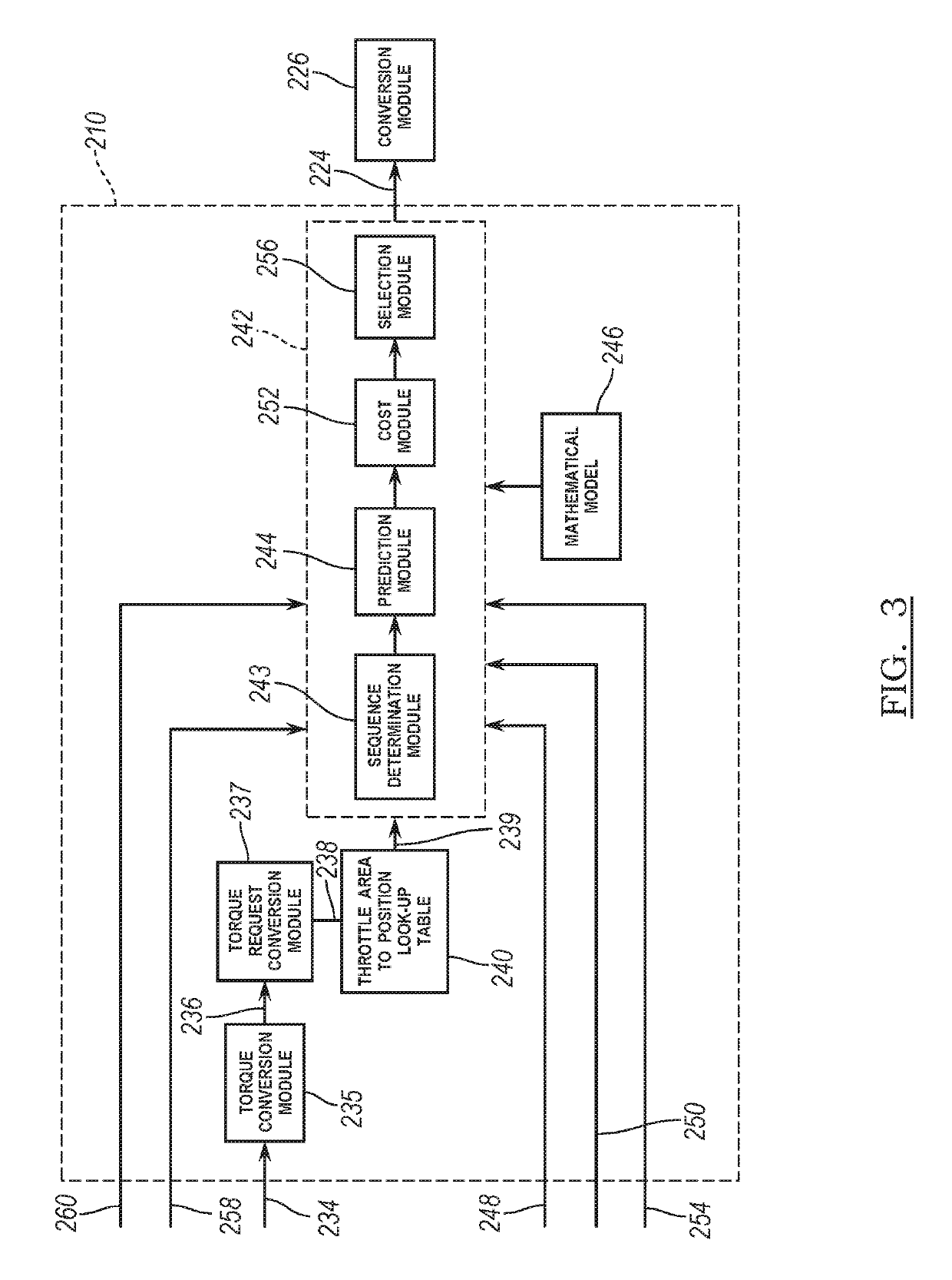
[0033]The following description is merely exemplary in nature and is not intended to limit the present disclosure, application, or uses.

[0034]An electronic throttle position control module of the present disclosure generates throttle target values using model predictive control (MPC). More specifically, the electronic throttle position control module identifies possible sets of throttle target values based on an electronic throttle position. The electronic throttle position control module determines predicted parameters for each of the possible sets based on the possible sets' target values and a mathematical model of the throttle body. For example, the electronic throttle position control module determines a predicted electronic throttle position for each of the possible sets of target values. The electronic throttle position control module also determines a cost associated with use of each of the possible sets. The cost determined for a possible set increases as a magnitude of a f...


PUM


Abstract

A vehicle throttle control system includes a torque control system providing a desired torque for a throttle valve. A conversion module converts the desired torque to a desired throttle area and converts the desired throttle area to a target throttle position. A selection module determines which one of multiple MPC controllers should be used based on a current position of the throttle valve. A prediction module determines future state values using a mathematical model of a throttle body. A cost module determines a first cost for a first set of MPC target throttle duty cycle values. A control module identifies optimal sets of target throttle motor duty cycle values for each of the MPC controllers. The multiple MPC controllers control operation of a throttle valve duty cycle to achieve a target throttle opening area based on a first one of the target throttle motor duty cycle values.

Description

INTRODUCTION[0001]The present disclosure relates to electric motors and more particularly to electronic throttle body control systems and methods for vehicles.[0002]Internal combustion engines combust an air and fuel mixture within cylinders to drive pistons, which produces drive torque. Air flow into the engine is regulated via a throttle. The throttle adjusts a throttle area, which increases or decreases air flow into the engine. As the throttle area increases, the air flow into the engine increases. A fuel control system adjusts the rate that fuel is injected to provide a desired air / fuel mixture to the cylinders and / or to achieve a desired torque output. Increasing the amount of air and fuel provided to the cylinders increases the torque output of the engine.[0003]Electronic throttle control systems have been developed to control a throttle valve position or area to achieve a desired torque. Many of these valves are motor actuated blade or butterfly valves having a valve default...

Claims


Application Information

Patent Timeline
Patent Type & Authority Patents(United States)
IPC IPC(8): F02D11/10F02D41/14F02D41/00G05B13/04F02D41/30
CPCG05B13/048F02D41/1406F02D11/105F02D11/10F02D41/0002F02D41/30F02D2041/142F02D2041/1412F02D2041/1413F02D2041/1417F02D2041/1423F02D2041/1431F02D2041/1433F02D2041/1418F02D41/1401F02D2041/0022F02D2011/104Y02T10/40
Inventor LEVIJOKI, STEPHEN P.XU, BINCIMINI, GIONATA
Owner GM GLOBAL TECH OPERATIONS LLC
Why Eureka
Try Eureka