
Thermal insulating system for high temperature industrial tanks and equipment

a technology for industrial tanks and thermal insulation systems, applied in the direction of thermal insulation, pipes/joints/fittings, containers, etc., can solve the problems of high transmission coefficient of metal elements with respect to equipment, negative influence of thermal insulation systems used, and heat loss

Active Publication Date: 2019-10-01
AISLAMIENTOS SUAVAL
View PDF10 Cites 0 Cited by
  • Summary
  • Abstract
  • Description
  • Claims
  • Application Information

AI Technical Summary

Benefits of technology

The system effectively absorbs thermal expansions and contractions, maintaining insulation quality, preventing water and air ingress, and reducing thermal losses, while ensuring the integrity and tightness of the covering system.

Problems solved by technology

However, in large-sized equipment, the expansion and contraction of this equipment, mainly tanks, the changes are very significant and they can affect negatively to the thermal insulating systems used.
The support elements for the thermal insulating materials and the covering system, should be minimized as much as possible, given that the soldering of these elements to the equipment may weaken the walls of said equipment; furthermore, the thermal transmission coefficient of these metal elements with respect to the equipment is very high, leading to heat losses.
The mere entrance of wind between covering sheets could cause the fastenings to burst and the covering sheets to come away.
With the breakage, rain water and wind can get inside and gradually deteriorate the insulating material, as well as the covering system.
First, when the omega clip absorbs the traction produced by the expansions, a decreasing of the thickness of the insulating materials occurs, diminishing the insulation quality, and putting the maintenance of the production process at risk.
Secondly, the omega clip can never absorb all of the traction, since it must have mechanical resistance to prevent it from breaking; as a result, the covering sheets continue to be subject to resisting forces that lead to breakage and joints.

Method used


Image

  • Thermal insulating system for high temperature industrial tanks and equipment
  • Thermal insulating system for high temperature industrial tanks and equipment
  • Thermal insulating system for high temperature industrial tanks and equipment

Examples


Embodiment Construction

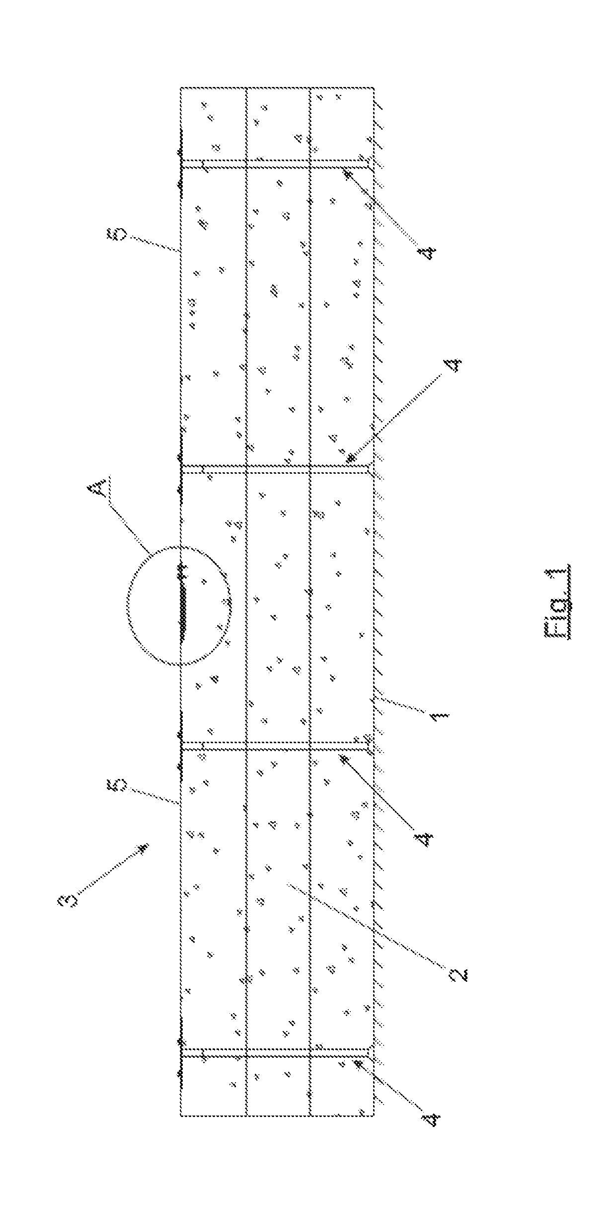
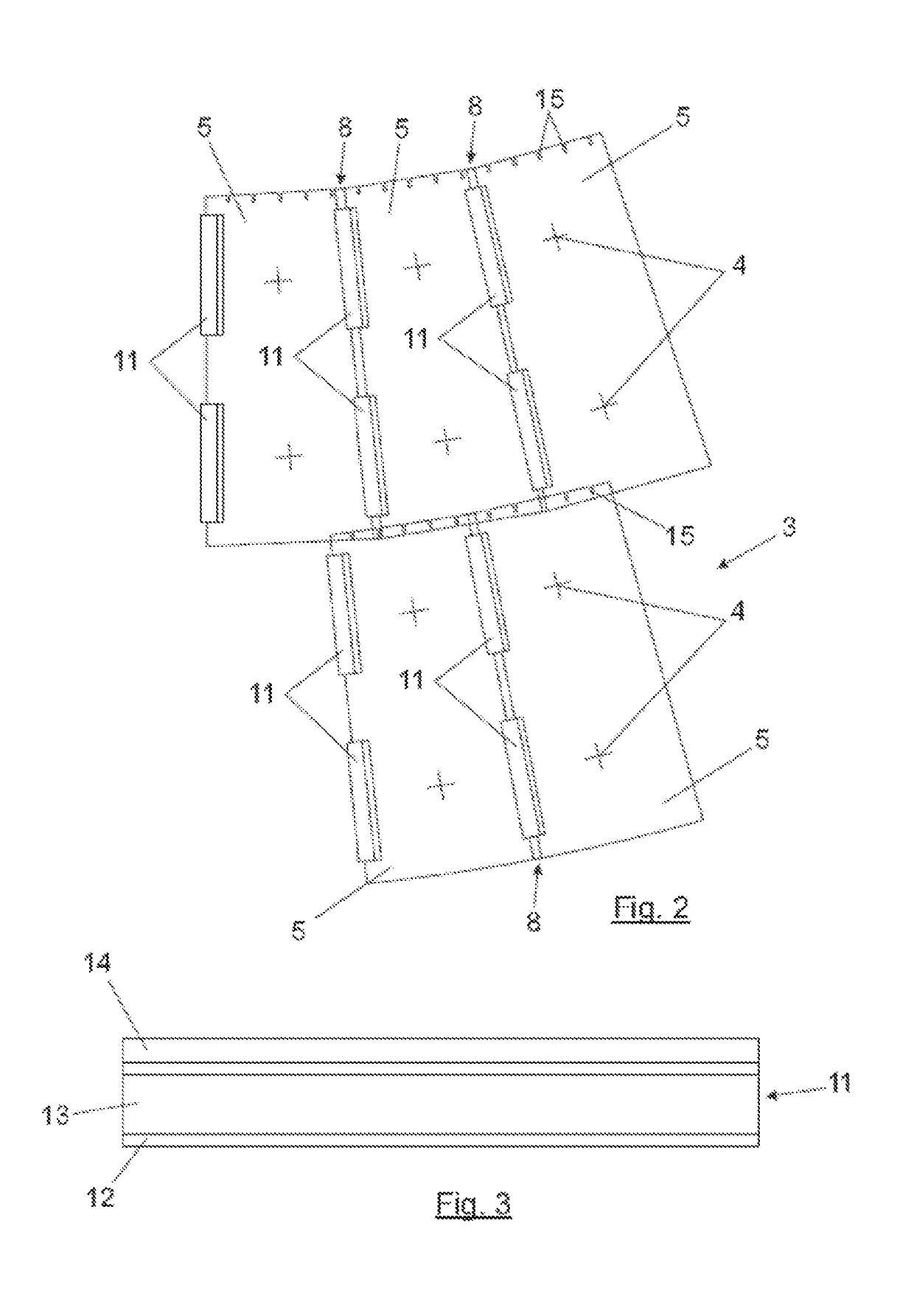
[0023]The present invention provides an advantage with respect to the current insulating systems for high temperature industrial equipment, providing a thermal insulating system for high temperature industrial tanks and equipment which can absorb these expansions and contractions of the tanks and equipment, while maintaining all insulating properties and requirements: keeping the designed insulation thickness, avoiding joints in the covering system and ensuring tightness and integrity in the insulating system.

[0024]This is achieved by means of a thermal insulation system for high temperature industrial tanks and equipment as disclosed in claim 1 of the present application.

[0025]This thermal insulating system comprises an insulating material which is placed on the walls of the industrial tanks and equipment, a covering system which covers the insulating material, and a support system which supports the insulating material and the covering system.

[0026]The covering system of the prese...


PUM


Abstract

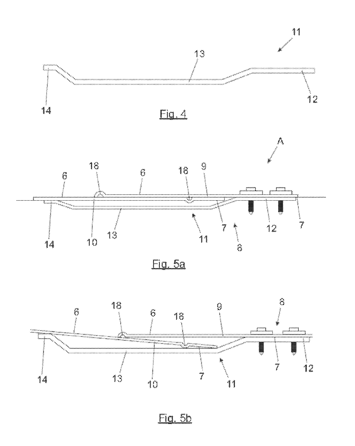
Thermal insulating system for high temperature industrial tanks and equipment, comprising thermal insulating material, a covering system and a support system. The covering system has covering sheets fixed only to the support system. Adjacent covering sheets overlap longitudinally giving rise to overlapped sections comprising an upper part from one of the adjacent covering sheets and a lower part from the other adjacent covering sheet. At least a substantially omega-shaped longitudinal assembly clip is placed at each overlapped section, on the interior sides of the covering sheets, which has a first end attached to the upper part, a central portion separated from the covering sheets, and a second end contacting the lower part of the overlapped section and pressing said lower part.

Description

CROSS REFERENCE TO RELATED APPLICATION[0001]This Application is a 371 of PCT / ES2015 / 070784 filed on Nov. 2, 2015, which is incorporated herein by reference.FIELD OF THE INVENTION[0002]The present invention is encompassed within the technical field of industrial facilities and equipment operating at high temperatures, such as equipment for thermal and thermosolar plants, chemical and petrochemical plants and so on, and specifically of thermal insulating systems for industrial tanks and equipment operating at high temperatures, said tanks and equipment suffering significant thermal expansions and contractions during the operation thereof.[0003]The invention relates, in particular, to a thermal insulating system for high temperature industrial tanks and equipment which can absorb these expansions and contractions of the tanks and equipment, while maintaining all insulating properties.BACKGROUND OF THE INVENTION[0004]Certain industrial production processes and facilities require that hi...

Claims


Application Information

Patent Timeline
Patent Type & Authority Patents(United States)
IPC IPC(8): F16L59/02B65D90/06F16L59/10F16L59/12F16L59/135
CPCF16L59/135F16L59/10F16L59/123B65D90/06F16L59/028
Inventor LOPEZ ALVAREZ, JOSE LUISAROZA SUAREZ, RAMONNAVARRO SUAY, LUIS MIGUELSUAREZ-VALDES SUAREZ, JOSE GUILLERMO
Owner AISLAMIENTOS SUAVAL
Learn More