
Explosive ordnance cold assembly process

a technology of explosive ordnance and assembly process, which is applied in the direction of weapons, ammunition, weapon components, etc., can solve the problems of periodic cracks or voids, system failure, and tremendous dynamic stress on payloads, and achieve the effect of preventing condensation of moisture, facilitating relative movement, and deteriorating the explosive body

Active Publication Date: 2019-08-13
SPECTRA TECH LLC
View PDF17 Cites 0 Cited by
  • Summary
  • Abstract
  • Description
  • Claims
  • Application Information

AI Technical Summary

Benefits of technology

[0005]When below the lowest anticipated product operating temperature the explosive body will be spaced or separated from the inner diameter of the projectile body preferably by a predetermined gap. This gap facilitates relative movement between the bodies while the bodies are being nested together. This exemplary process may include placing the explosive body within a chamber containing a dry gas such as an inert gas prior to cooling the explosive body and nesting the explosive body within the hollow projectile body. This prevents condensation of moisture from air collecting on the cooled explosive body and deteriorating the explosive body or accelerating corrosion during the life cycle of the ordnance. The desired temperature below the lowest anticipated operating temperature is generally between −70 and −40 degrees Fahrenheit, and may preferably be in a range of between −60 and −50 degrees Fahrenheit. The act of securing may include closing the explosive body within the projectile body with a bulkhead or sealing disc, fuse holder, or other closure device. The process may also include normalizing the temperatures of the secured explosive and projectile bodies at a controlled rate.
[0006]A projectile formed by the above exemplary process will result in the projectile body applying a substantially constant compression against the explosive body across the anticipated temperature range of the projectile during its life cycle and avoids unbalancing the projectile by changes of center of gravity or other asymmetries which might result from mismatch of the inner explosive body to the outer projectile body. Where the inner explosive body that has some plasticity, the constant compression provides intimate contact with all interior geometries which may be mismatched slightly due to machining, metal forming, molding or other processes which otherwise might create gross or slight discontinuities.
[0007]Compression loading in accordance with the process described herein ensures no gaps, either crack or voids, even small unanticipated voids can form or propogate, through the performance temperature range of the ordnance, which ensures that problems associated with adiabatic compression are eliminated, either during energetics component loading, projectile storage, handling, launch or during target entry. Furthermore, elimination of mass movement inside of a penetration weapon projectile provides for greater fuse survivability during target entry, most especially that which is related to tail slap, where the explosive body itself is no longer allowed to accelerate into the fuse structures. In addition, the new processing approach in accordance with the present disclosure is anticipated to prevent latent effects due to environmental stresses from impacting functionality and eliminate the impact of those realized through or during normal loading processes when the compressive approach described herein is utilized.

Problems solved by technology

These payloads undergo tremendous dynamic stresses during acceleration within either a smooth or rifled barrel of the weapon.
It is often virtually impossible to prevent formation and inclusion of small internal void spaces and undetectable cracks in the explosive charge body which can lead to system failure in the event of an unanticipated shock load.
Furthermore, some energetics loading processes are prone to periodically yield cracks or voids.
Traditional thermal cycling and field use also may create cracks consequently requiring surveillance programs on the polymeric components as the polymers age.

Method used


Image

  • Explosive ordnance cold assembly process
  • Explosive ordnance cold assembly process
  • Explosive ordnance cold assembly process

Examples


Embodiment Construction

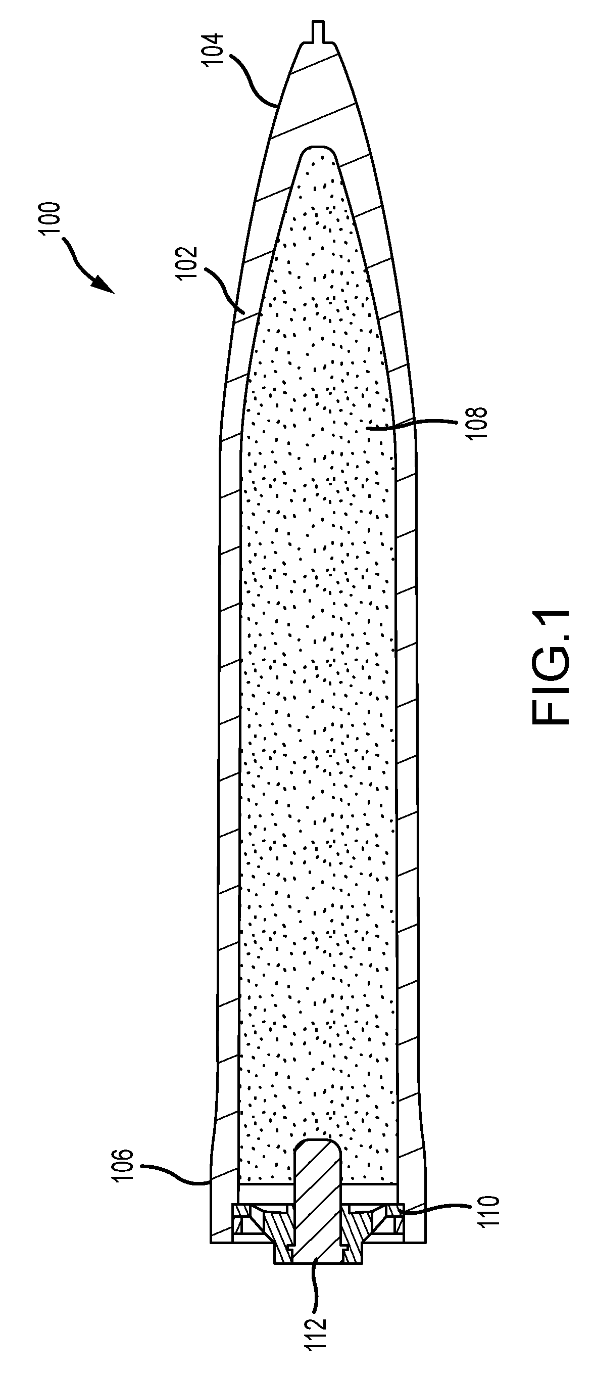
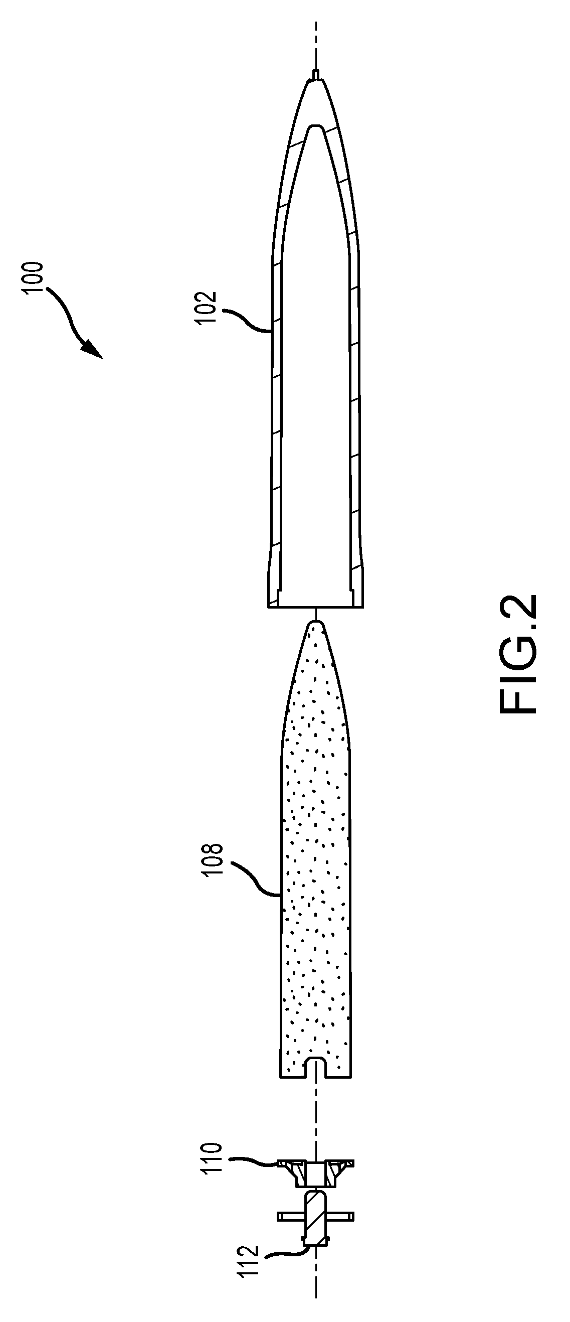
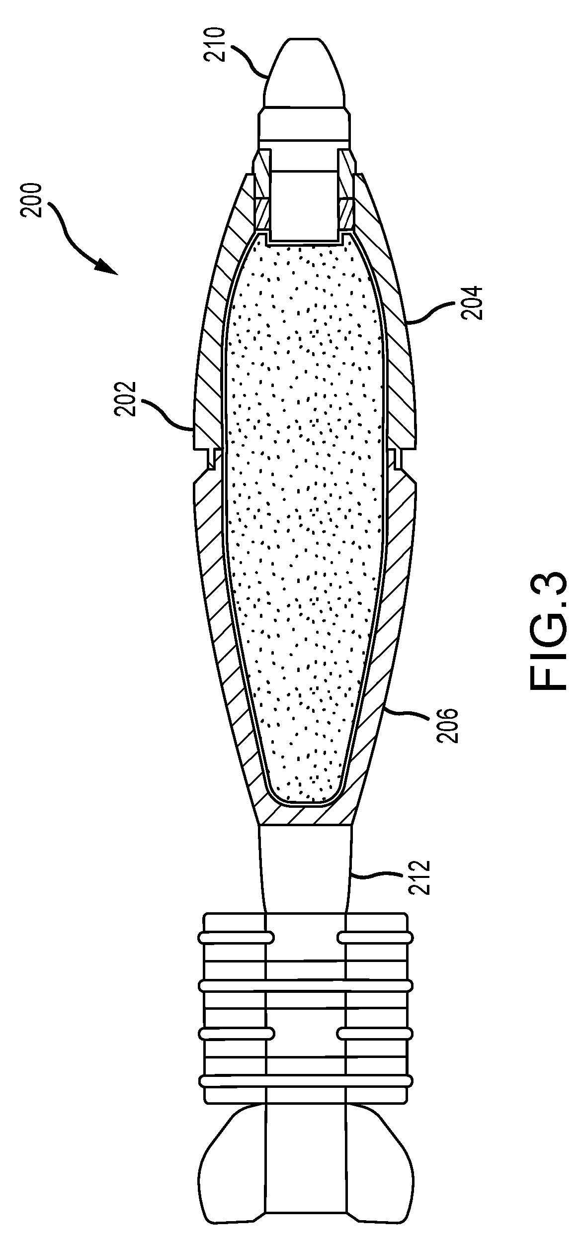
[0017]A first exemplary embodiment of a projectile 100 assembled in accordance with one embodiment of the process of the present disclosure is shown schematically in a longitudinal sectional view in FIG. 1. The projectile 100 has a hollow, generally tubular frangible projectile body 102 having a pointed closed nose 104 and an open rear 106. The projectile body 102 is typically made of a steel or other strong metal material and has a characteristic coefficient of thermal expansion (CTE) for that material.

[0018]The projectile body 102 contains an explosive charge body 108 such as a RDX, CDX or other explosive which may be in the form of a solid body or other form that is encapsulated in an solid enclosure such as a polyethylene liner so as to have a shape complementary to the internal shape or contour of the projectile body 102. The explosive charge body or package 108 as a whole also has a characteristic CTE because it will tend to expand or contract its outer dimensions with changes...


PUM


Abstract

An assembly process is described for producing an ordnance projectile wherein the projectile maintains a compressive force on an explosive body carried therein throughout an anticipated operational temperature range. The process includes raising the temperature of the hollow projectile body to an elevated temperature, cooling the explosive body to a temperature below a lowest anticipated operating temperature of the projectile, nesting the cooled explosive body within the hollow projectile body while the projectile is at the elevated temperature, securing the explosive body and the hollow projectile body together, and normalizing the temperature of the nested bodies by allowing them to come to a common temperature, typically room temperature. Different thermal expansion characteristics of the inner and outer bodies will result in the projectile maintaining a compressive force on the explosive body at normal temperatures.

Description

CROSS REFERENCE TO RELATED APPLICATIONS[0001]This application claims the benefit of priority of U.S. Provisional Patent Application Ser. No. 62 / 577,533 filed Oct. 26, 2017, the content of which is incorporated by reference herein in its entirety.BACKGROUND OF THE DISCLOSURE[0002]Projectiles fired from conventional military weapons often carry energetic payloads made up of nested components and subcomponents, one within another. Energetic payloads often include explosives that may be initiated by physical impact with a target. These payloads undergo tremendous dynamic stresses during acceleration within either a smooth or rifled barrel of the weapon. If the nested components are not solidly in contact with each other during this acceleration, spontaneous ignition of the energetic components can become a real possibility. Such stresses also occur during deceleration for projectiles designed to penetrate within a target before detonation. Consequently, precise component tolerances of s...

Claims


Application Information

Patent Timeline
Patent Type & Authority Patents(United States)
IPC IPC(8): F42B33/02
CPCF42B33/0207
Inventor SIGGERS, DAVID L.
Owner SPECTRA TECH LLC
Learn More