
Hospital bed

a bed and hospital technology, applied in the field of beds, can solve the problems of reducing the handling and transportation of people, and achieve the effects of improving the upgradeability, substantial flexibility, and facilitating the addition or removal of modules

Inactive Publication Date: 2006-03-28
HILL ROM SERVICES
View PDF94 Cites 211 Cited by
  • Summary
  • Abstract
  • Description
  • Claims
  • Application Information

AI Technical Summary

Benefits of technology

[0003]Many hospital beds are positionable to a configuration having the sleeping surface of the bed at a predetermined height above the floor and having siderails positioned to restrain the movement of a person lying on the sleeping surface past sides of the sleeping surface and off of the bed. The sleeping surfaces of many such hospital beds can typically be lowered to reduce the distance between the sleeping surface and the floor, and the sleeping surfaces of such beds can often be manipulated to adjust the position of the person on the sleeping surface. In addition, the siderails of these hospital beds can typically be moved to a position away from the sleeping surface to facilitate movement of the person on the sleeping surface from the supine position on the sleeping surface to a standing position on the floor near the bed.
[0123]Preferably, the length of the surface foot section is reduced by at least 40% when the first and second air bladders are deflated and the thickness of the surface foot section is reduced by at least 80% when the first and second air bladders are deflated. This feature maintains an appropriate size for a seat section of the chair and permits a patient's feet to touch the floor when the bed is in the chair configuration. The foot deck section is movable from an extended position to a retracted position to shorten the foot deck section as the articulating deck moves to the chair configuration.

Problems solved by technology

This flexibility results in reduced handling and transport of the person since mobility can be provided closer to the stretcher, and the person can stay on one bed for transport so that seamless care can be provided.

Method used


Image

  • Hospital bed
  • Hospital bed
  • Hospital bed

Examples


first embodiment

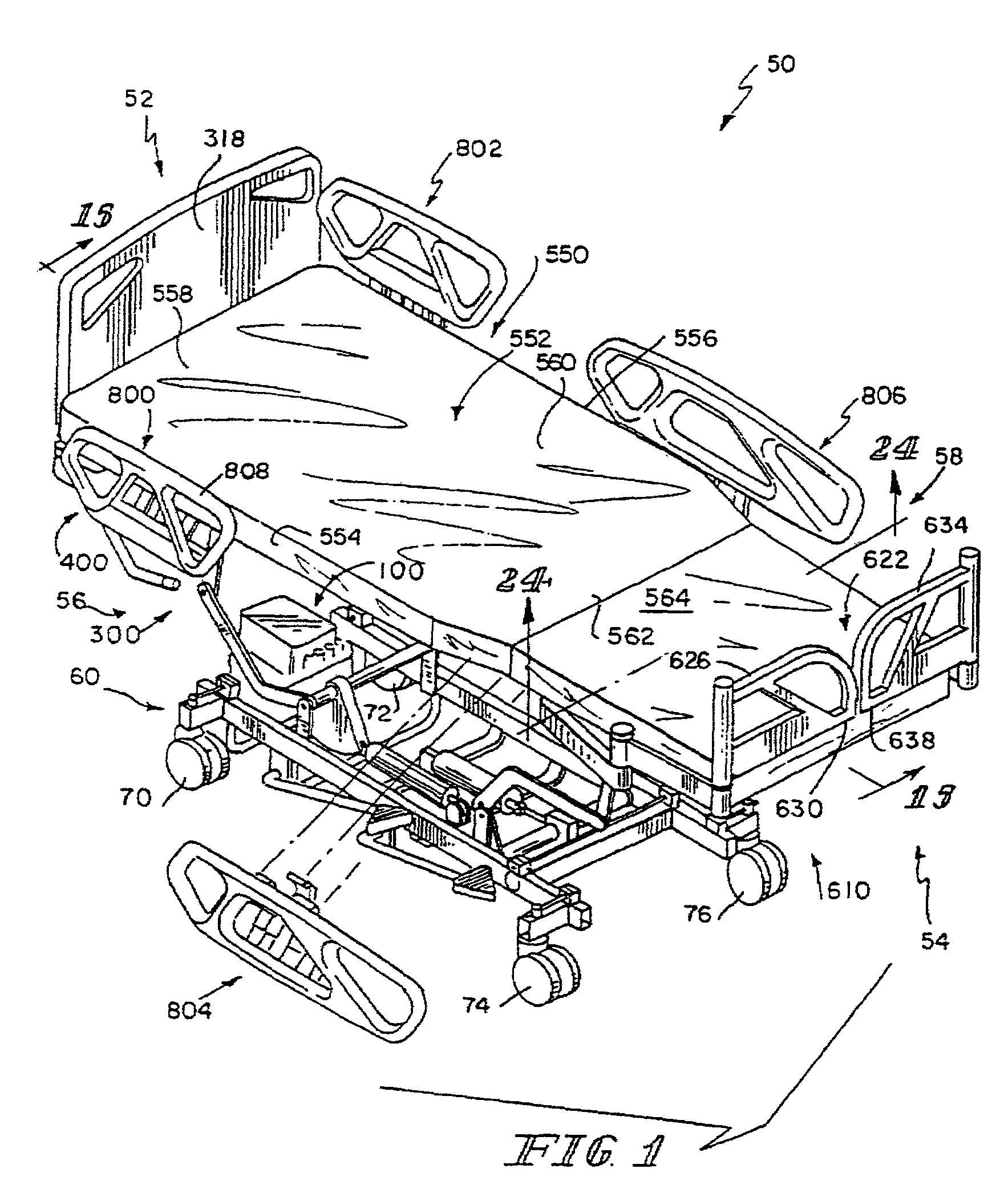
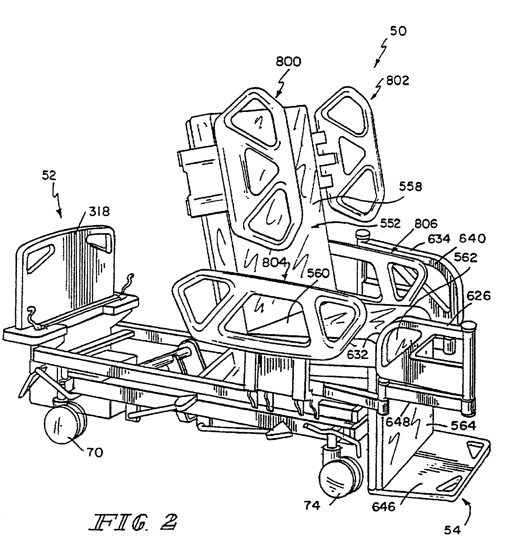
[0361]a chair bed 50 in accordance with the present invention additionally includes thigh section 408 of articulating deck 402 which is configured to pivot relative to weigh frame 506 as shown in FIG. 15. Thigh section 408 pivots about a pivot axis 602 adjacent to head end 52 of thigh section 408 between a down position in which thigh section 408 is generally horizontal and parallel to weigh frame 506 and an upward position in which foot end 54 of thigh section 408 is elevated above weigh frame 506. Thigh section pivot cylinder 158 is connected to weigh frame 506 as shown in FIGS. 14 and 15. Although thigh section 408 can move independently of the head and foot sections 404, 410, thigh section 408 preferably moves to the upward position when head section 404 moves to the back-support position so that the head and thigh sections 404, 408 cooperate to cradle the person (not shown) on sleeping surface 552 therebetween. Thigh section 408 preferably moves to the down position when head s...

second embodiment

[0373]a contracting mechanism 520 for expanding and contracting the length of foot section 410 can illustratively be operated using an air control system 522 that also operates to inflate and deflate foot portion 564 of mattress 550 as shown in FIG. 25a. Air control system 522 includes an air supply 524 for supplying pressurized air and a controller 526 for controlling the flow of air through conduit 528 to inflatable foot portion 564 and to contracting mechanism 520.

[0374]Contracting mechanism 520 includes a bellows 530 that is received between a first wall 534 that is fixed to pivoting member 466 and a second wall 536 that is fixed to contracting member 462 as shown in FIG. 25a. Contracting member 462 is slidably connected to pivoting member so that second wall 536 can slide relative to first wall 534. As second wall 536 moves toward first wall 534, contracting member is drawn inwardly to contract foot section 410. As second wall is pushed away from first wall 534, contracting mem...


PUM


Abstract

A method is provided for permitting a module which is configured to perform a dedicated function on a bed to use a graphical interface. Graphic format data used by the module is downloaded, if necessary, and stored in a memory of the graphical interface.

Description

RELATED APPLICATIONS[0001]This application is a continuation of U.S. patent application Ser. No. 09 / 655,127, filed Sep. 5, 2000, now U.S. Pat. No. 6,336,235, which is a continuation of U.S. patent application Ser. No. 09 / 018,542, filed Feb. 4, 1998, now U.S. Pat. No. 6,163,903, which is a continuation of U.S. patent application Ser. No. 08 / 511,711, filed Aug. 4, 1995, now U.S. Pat. No. 5,715,548, the disclosures of which are expressly incorporated by reference herein.BACKGROUND AND SUMMARY OF THE INVENTION[0002]The present invention relates to a bed, and particularly to a chair bed that can be manipulated to achieve both a conventional bed position having a horizontal sleeping surface upon which a person lies in a supine position and a sitting position having the feet of the person on or adjacent to the floor and the head and back of the person supported above a seat formed by the bed. More particularly, the present invention relates to a hospital bed or a patient-care bed which is ...

Claims


Application Information

Patent Timeline
IPC IPC(8): A61G7/00A47C17/17A61G5/14A61G7/002A61G7/005A61G7/008A61G7/012A61G7/015A61G7/02A61G7/05A61G7/053A61G7/10A61H3/04
CPCA61G7/002A61G7/005A61G7/008A61G7/012A61G7/015A61G7/018A61G7/0507A61G7/053A61G7/05776A61G7/16H04L67/12A61G7/0506A61G7/00A61G5/14A61G2203/20A61G7/05A61G7/05769A61G2007/0509A61G2007/0514A61G2007/0524A61G2007/0527A61G2007/0528A61G2200/56A61G2203/32A61G2203/74A61G2210/50G06F19/3418A61G7/0509A61G7/0514A61G7/0524A61G7/0527A61G7/0528G16H40/67
Inventor WEISMILLER, MATTHEW W.KUMMER, JOSEPH A.KRAMER, KENNETH L.SCHULTE, STEPHEN R.PALERMO, PHILIP D.DLUGOS, JR., DANIEL F.
Owner HILL ROM SERVICES
Learn More