
Method using heat pipes with multiple evaporator/condenser zones and heat exchangers using same

a heat exchanger and heat pipe technology, applied in lighting and heating apparatus, ventilation systems, heating types, etc., can solve the problems of reducing limiting the physical construction of proper operation, and affecting the efficiency of large tubes, so as to reduce the pressure drop and subsequent energy penalty

Active Publication Date: 2019-08-06
KENTUCKIANA CURB
View PDF3 Cites 0 Cited by
  • Summary
  • Abstract
  • Description
  • Claims
  • Application Information

AI Technical Summary

Benefits of technology

[0015]It is therefore an object of the present invention to use smaller diameter tube heat pipes with an airflow arrangement that allows for short distances between multiple, adjacent evaporating and condensing sections of the heat pipe.
[0016]It is also an object to increase the overall tube length indefinitely, without traditional degradation of performance, either as a straight tube or as a serpentine tube with undulating pipes.

Problems solved by technology

While heat pipes are relatively inexpensive to manufacture and offer orders of magnitude effective thermal conductivity as compared to solid copper of similar size, there are some limitations to their physical construction for proper operation.
Heat pipes typically degrade in performance as the tube length increases.
Increasing tube diameter can help alleviate this issue, but larger tubes come with their own inefficiencies.

Method used


Image

  • Method using heat pipes with multiple evaporator/condenser zones and heat exchangers using same
  • Method using heat pipes with multiple evaporator/condenser zones and heat exchangers using same
  • Method using heat pipes with multiple evaporator/condenser zones and heat exchangers using same

Examples


Embodiment Construction

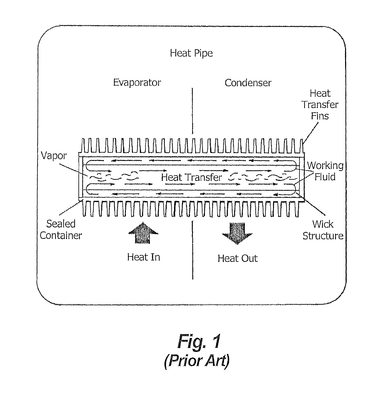
[0045]FIG. 1 illustrates the operation of a typical prior art heat pipe with a single divider externally separating evaporator from the condenser section. Note the one-way internal vapor flow to the right in the open center and the reverse liquid flow in the wick.

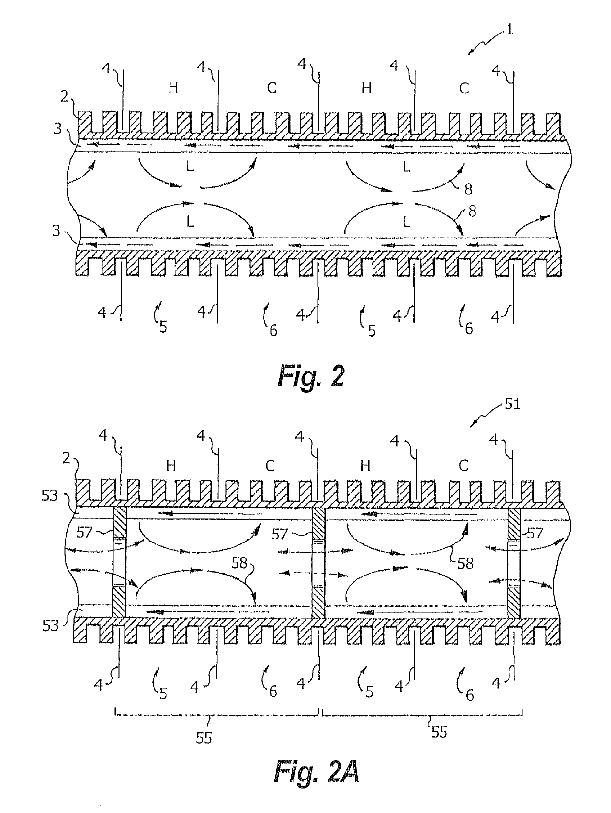
[0046]FIG. 2 shows a section of heat pipe using the multiple adjacent evaporator / condenser (hot / cold) sections method along the entire length of a heat pipe 1. The outer side 2 is shown as a rigid finned tube with an internal wick 3 bonded to it. Baffles or partitions 4 keep the external hot 5 and cold 6 flows or regions separated. Vapor 8 evaporates into the central section and partitions into a right and a left drift to the adjacent cold condensing section 6 from each hot evaporating section 5. FIG. 2 also shows the direction of liquid flow within wick 3 in both directions toward adjacent evaporator 5 sections. This flow generates short loops of vapor / liquid within the heat pipe, which negates the inherent inefficiency as...


PUM


Abstract

Elongated, smaller-diameter tube heat pipes have an airflow arrangement that allows for short distances between evaporating and condensing sections of the heat pipe. The heat pipe is exposed to multiple alternate hot and cold zones adjacent to each other. Each evaporator zone accepts input heat to cause evaporation of the working fluid in the wick of the immediate vicinity. The vapor produced moves to either side by local pressure differences to condense in the two adjacent condenser zones where it is absorbed by the wick as a liquid and flows in the wick back to adjacent evaporator zones at each side. Each evaporator zone creates two fluid loops whereby evaporated working fluid splits up left and right, condenses in adjacent condenser zones and flows back to the evaporator zone as a liquid within the wick. Therefore, the overall tube length can be increased indefinitely, without traditional degradation of performance.

Description

RELATED APPLICATIONS[0001]This application is a continuation-in-part of application Ser. No. 13 / 317,660, filed Oct. 25, 2011, (the '660 application) and claims priority under 35 USC § 120 therefrom. The '660 application is incorporated by reference herein.FIELD OF THE INVENTION[0002]The present invention relates to using efficient small diameter heat pipes with multiple evaporator / condenser zones in a single heat pipe.BACKGROUND OF THE INVENTION[0003]Heat pipe technology is old art incorporating the use of an evacuated sealed metal pipe partially filled with a working fluid. A wide variety of working fluids may be used; they are selected to be compatible with the temperature regime of the two heat transfer pairs between which heat is being transferred. The heat source must be able to evaporate the working fluid while the heat sink must be able to condense the vapor back into a liquid. Heat pipes also typically contain an internal wick coating to return condensed working fluid back t...

Claims


Application Information

Patent Timeline
Patent Type & Authority Patents(United States)
IPC IPC(8): F28D15/04F28F13/08F28D15/02F28F1/26F24F12/00F28F1/32
CPCF28D15/04F28D15/0275F28F13/08Y02B30/563F28F1/26F28F1/32F24F2012/005Y02B30/56
Inventor STARK, WALTER
Owner KENTUCKIANA CURB
Learn More