
Heat pump and its coil

A heat pump and coil technology, applied in the field of heat pumps and their coils, can solve problems such as affecting evaporation temperature and compressor mass flow, local liquid accumulation and uneven flow distribution, inability to design heat exchangers, etc., so as to increase the tube length. , the tube length is low, the effect of reducing the pressure drop

Active Publication Date: 2017-03-01
TRANE AIR CONDITIONING SYST (CHINA) CO LTD
View PDF7 Cites 0 Cited by
  • Summary
  • Abstract
  • Description
  • Claims
  • Application Information

AI Technical Summary

Problems solved by technology

In terms of flow rate, when used as an evaporator, the flow rate is high (the outlet flow rate is about 3 times that of the inlet flow rate when used as a condenser, and the inlet dryness is about 20%), and the pressure drop is large, which affects the evaporation temperature and the mass flow rate of the compressor. ; When used as a condenser, the flow rate is low, and a section needs to be taken as subcooling at the same time, which will easily lead to local liquid accumulation and uneven flow distribution
The existing coil heat exchanger has one inlet and one outlet, and the flow direction when it is used as a condenser is just opposite to that of an evaporator, so a compromise needs to be made between the condensation heat transfer effect and the evaporation heat transfer effect during the design process Considering that the heat exchanger cannot be designed like a cooling-only system

Method used


Image

  • Heat pump and its coil
  • Heat pump and its coil

Examples


Embodiment Construction

[0019] The present invention will be further described below in conjunction with specific embodiment and accompanying drawing, set forth more details in the following description so as to fully understand the present invention, but the present invention can obviously be implemented in many other ways different from this description, Those skilled in the art can make similar promotions and deductions based on actual application situations without violating the connotation of the present invention, so the content of this specific embodiment should not limit the protection scope of the present invention.

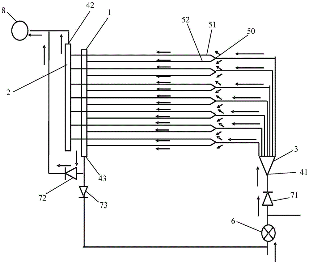
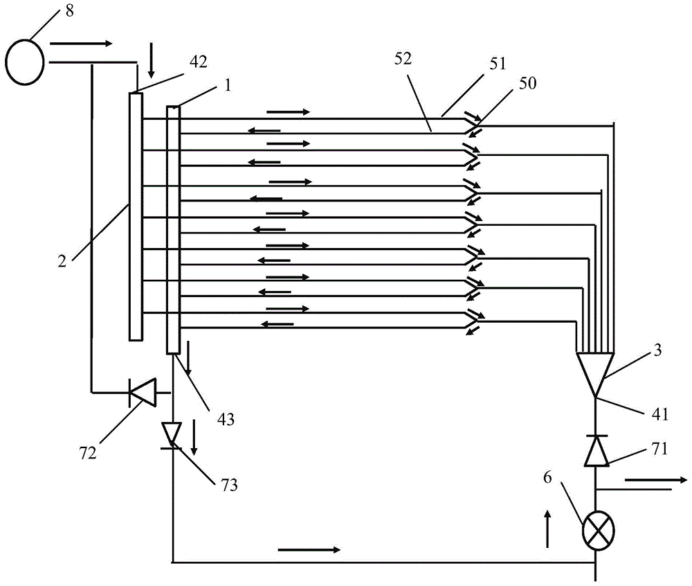
[0020] In an embodiment of the present invention, the heat pump includes a compressor, at least two heat pump coils, a four-way valve and an expansion valve. exist figure 1 with figure 2 The compressor is omitted in the figure, and only one heat pump coil is shown. The other heat pump coils not shown can be configured according to the structure and principle of the heat pump ...


PUM


Abstract

The invention provides a heat pump and its coil, which improves the heat exchange effect of the heat exchanger in which the coil serves as both an evaporator and a condenser. The evaporation path of the heat pump coil is that the liquid refrigerant enters the refrigerant distributor through the first interface for distribution, then passes through the three-way device, enters the first branch and the second branch respectively, and the refrigerant that passes through the first branch evaporates Then it flows out from the second interface of the second header, and the refrigerant that passes through the second branch evaporates and flows out from the third interface of the first header, and flows out after merging with the refrigerant from the second interface; the heat pump The condensation path of the coil is that the gaseous refrigerant flows into the second header from the second interface, then flows into the first branch, passes through the three-way device, turns to enter the second branch, and then enters the first header. The third interface of a collecting pipe flows out.

Description

technical field [0001] The invention relates to a heat pump and its coil. Background technique [0002] When designing the heat pump unit, it is necessary to take into account the heat exchange effect when the heat exchanger coil is a condenser and the heat exchange effect when it is an evaporator. In terms of flow rate, when used as an evaporator, the flow rate is high (the outlet flow rate is about 3 times that of the inlet flow rate when used as a condenser, and the inlet dryness is about 20%), and the pressure drop is large, which affects the evaporation temperature and the mass flow rate of the compressor. ; When used as a condenser, the flow rate is low, and a section needs to be taken as subcooling at the same time, which will easily lead to local liquid accumulation and uneven flow distribution. The existing coil heat exchanger has one inlet and one outlet, and the flow direction when it is used as a condenser is just opposite to that of an evaporator, so a compromi...

Claims


Application Information

Patent Timeline
Patent Type & Authority Patents(China)
IPC IPC(8): F25B30/00F25B39/00F25B41/06F25B41/31
CPCF25B39/00F25B41/37F25B41/20
Inventor 杜玉清苏鹏
Owner TRANE AIR CONDITIONING SYST (CHINA) CO LTD
Learn More