
Flash evaporator and air conditioner including flash evaporator

A flash evaporator and port technology, applied in the field of fluid heat exchange, can solve the problems of no subcooling of liquid refrigerant and low overall energy efficiency ratio, and achieve the effect of improving energy efficiency ratio

Active Publication Date: 2015-05-20
GREE ELECTRIC APPLIANCES INC
View PDF5 Cites 0 Cited by
  • Summary
  • Abstract
  • Description
  • Claims
  • Application Information

AI Technical Summary

Problems solved by technology

[0005] The present invention aims to provide a flash evaporator and an air conditioner including the flash evaporator, so as to solve the problems in the prior art that the liquid refrigerant flowing out of the flash evaporator has no supercooling degree, and the gaseous refrigerant has no superheating degree, resulting in relatively low overall energy efficiency ratio. technical issues

Method used


Image

  • Flash evaporator and air conditioner including flash evaporator
  • Flash evaporator and air conditioner including flash evaporator
  • Flash evaporator and air conditioner including flash evaporator

Examples


Embodiment 1

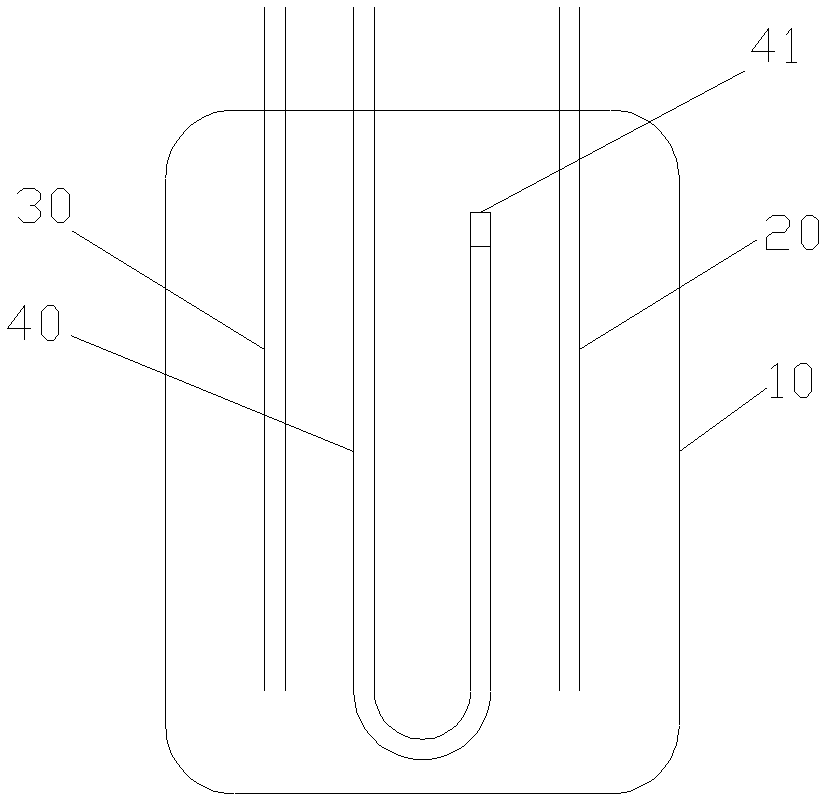
[0025] Such as figure 1 As shown, the flash evaporator of the present invention has a cylinder body 10, and the upper end of the cylinder body 10 is inserted into the cylinder body 10 respectively, and the lower end ports are respectively inserted into the liquid inlet pipe 30 and the liquid outlet pipe 20 in the cylinder body 10 and one end Located outside the cylinder block 10, the other end is located in the air outlet pipe 40 in the cylinder body, the lower end ports of the liquid inlet pipe 30 and the liquid outlet pipe 20 are inserted into the bottom of the cylinder block 10, and the air outlet pipe 40 has a cylinder with a position lower than the air outlet pipe 40. body internal port, and the position is lower than the lower pipe section of the lowest liquid level in the cylinder body 10, the lower pipe section is preferably a U-shaped pipe section or a V-shaped pipe section, and preferably, the bottom position of the lower pipe section is lower than the lower end port ...

Embodiment 2

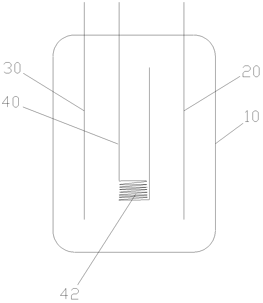
[0030] Such as image 3 As shown, the difference between the flash evaporator of the present invention and the structure in Embodiment 1 is that the length of the low-level pipe section is increased by setting the spirally wound pipe section 42 on the low-level pipe section. Preferably, the spirally wound pipe section 42 is located on the low-level pipe section , and communicate with the lower pipe section. And because the temperature of the lower layer of the liquid refrigerant in the cylinder 10 is lower than the temperature of the upper layer, the lower end of the coiled pipe section 42 is preferably connected to the inner port of the cylinder body of the gas outlet pipe 40 .

[0031] The flash evaporator of the present invention is provided with a coiled pipe section 42 on the outlet pipe 40, thereby increasing the length of the outlet pipe 40 soaked in the liquid refrigerant, which not only plays a throttling role, but also enhances the connection between the gaseous refr...

Embodiment 3

[0033] Such as Figure 4 As shown, the flash evaporator of the present invention is not only provided with a constriction 41 or a short capillary tube at the lower end port of the outlet pipe 40, but also provided with a coiled pipe section 42 at the bottom of the lower pipe section, so that the flash evaporator of the present invention The evaporator combines the advantages of the first embodiment and the second embodiment, better achieves the throttling effect and increases the energy efficiency ratio.

[0034] The constriction 41 or short capillary tube in the present invention, or the coiled pipe section 42 can also be arranged at other positions on the air outlet pipe 40, as long as the purpose of throttling can be achieved, and will not be repeated here.

[0035] In order to achieve a better throttling effect, the air outlet pipe 40 in the present invention is preferably a copper pipe, especially a copper pipe with a small diameter.

[0036] The present invention also p...


PUM


Abstract

The invention provides a flash evaporator and an air conditioner including the flash evaporator. The flash evaporator is provided with a cylinder body, wherein a liquid inlet pipe, a liquid outlet pipe and an exit pipe are inserted into the cylinder body; a first end port of the liquid inlet pipe, a first end port of the liquid outlet pipe and a first end port of the exit pipe protrude out of the cylinder body respectively; a second end port of the liquid inlet pipe ,a second end port of the liquid outlet pipe and a second end port of the exit pipe are positioned in the cylinder body respectively; the exit pipe is provided with a low position pipe section; the position of the low position pipe section is lower than the second end port of exit pipe and lower than the lowest liquid level in the cylinder body; throttle structures / a throttle structure are / is arranged on the low position pipe section and / or at the second end port of the exit pipe and / or at the position between the lower position pipe section and the second end port of the exit pipe. Through adopting the structure of the invention, the temperature of the gas refrigerant subjected to throttling is lower than that of the liquid refrigerant, so that the heat of the liquid refrigerant is absorbed by the gas refrigerant to enable the liquid refrigerant in the liquid outlet pipe to have a certain degree of supercooling and the gas refrigerant in the exit pipe to have a certain degree of superheating; the energy efficiency ratio is improved.

Description

technical field [0001] The invention relates to the technical field of fluid heat exchange, in particular to a flash evaporator and an air conditioner including the flash evaporator. Background technique [0002] At present, the two-stage compression system of the air conditioner generally adopts the flash evaporator to improve the function of cooling and heating, so as to improve its own energy efficiency ratio. The flash evaporator is an important part of the air conditioner. [0003] However, the structure of the existing flash evaporator is similar to the gas-liquid separator, which simply separates the refrigerant into saturated gas and saturated liquid. The separated saturated liquid enters the condenser and evaporator for heat exchange, while the saturated gas is directly fed back to the second-stage compression system of the compressor. [0004] With this structure of the flash evaporator, the enthalpy of the saturated liquid flowing out of the flash evaporator can ...

Claims


Application Information

Patent Timeline
Patent Type & Authority Patents(China)
IPC IPC(8): F25B43/00
Inventor 王现林张辉陈绍林叶泽波
Owner GREE ELECTRIC APPLIANCES INC
Learn More