Inverter module for driving a plurality of compressors and method for controlling the same

a technology of compressors and inverters, applied in the direction of dynamo-electric converter control, piston pumps, positive displacement liquid engines, etc., can solve the problems of excessive application, and achieve the effects of low cooling power, high cooling power, and high power control

Active Publication Date: 2019-08-06
LG ELECTRONICS INC
View PDF28 Cites 0 Cited by
  • Summary
  • Abstract
  • Description
  • Claims
  • Application Information

AI Technical Summary

Benefits of technology

[0037]According to an inverter module according to an embodiment disclosed in the present disclosure, there is an advantage that two linear compressors are driven with one inverter module including three upper arm elements and three lower arm elements.
[0038]In particular, according to an inverter module according to an embodiment disclosed in the present disclosure, there is an advantage that two linear compressors are driven in a half-bridge configuration and in a full-bridge configuration, respectively, in a low load operation mode requiring a relatively low cooling power to allow independent driving frequency control, and the two linear compressors are both driven in a fullbridge configuration in a high load operation mode requiring a relatively high cooling power to allow high power control.

Problems solved by technology

On the other hand, for the reciprocating compressor, particularly, linear compressor, the piston collides a cylinder wall or the piston is unable to move forward due to a large load not to properly perform compression when a voltage is abruptly, excessively applied since the piston performs a reciprocating movement while not being mechanically restricted within the cylinder.

Method used


Image

  • Inverter module for driving a plurality of compressors and method for controlling the same
  • Inverter module for driving a plurality of compressors and method for controlling the same
  • Inverter module for driving a plurality of compressors and method for controlling the same

Examples


Embodiment Construction

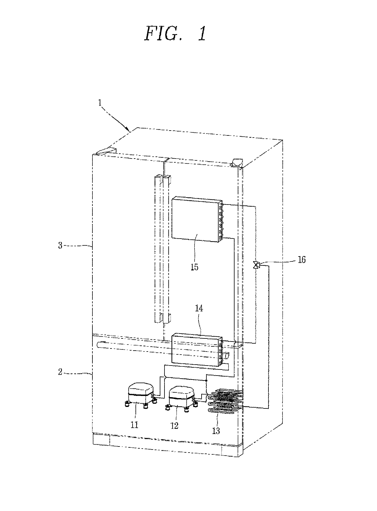
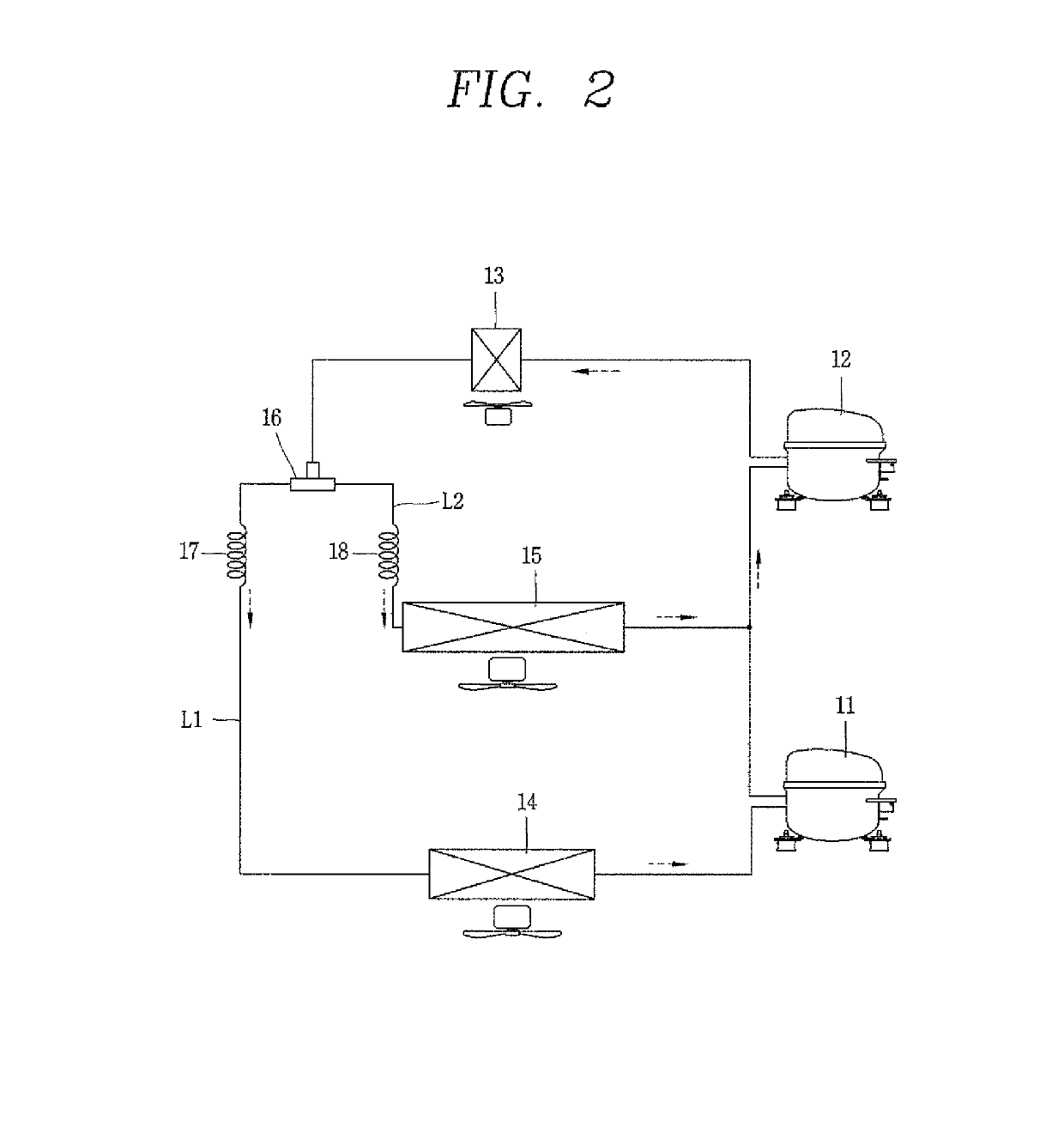
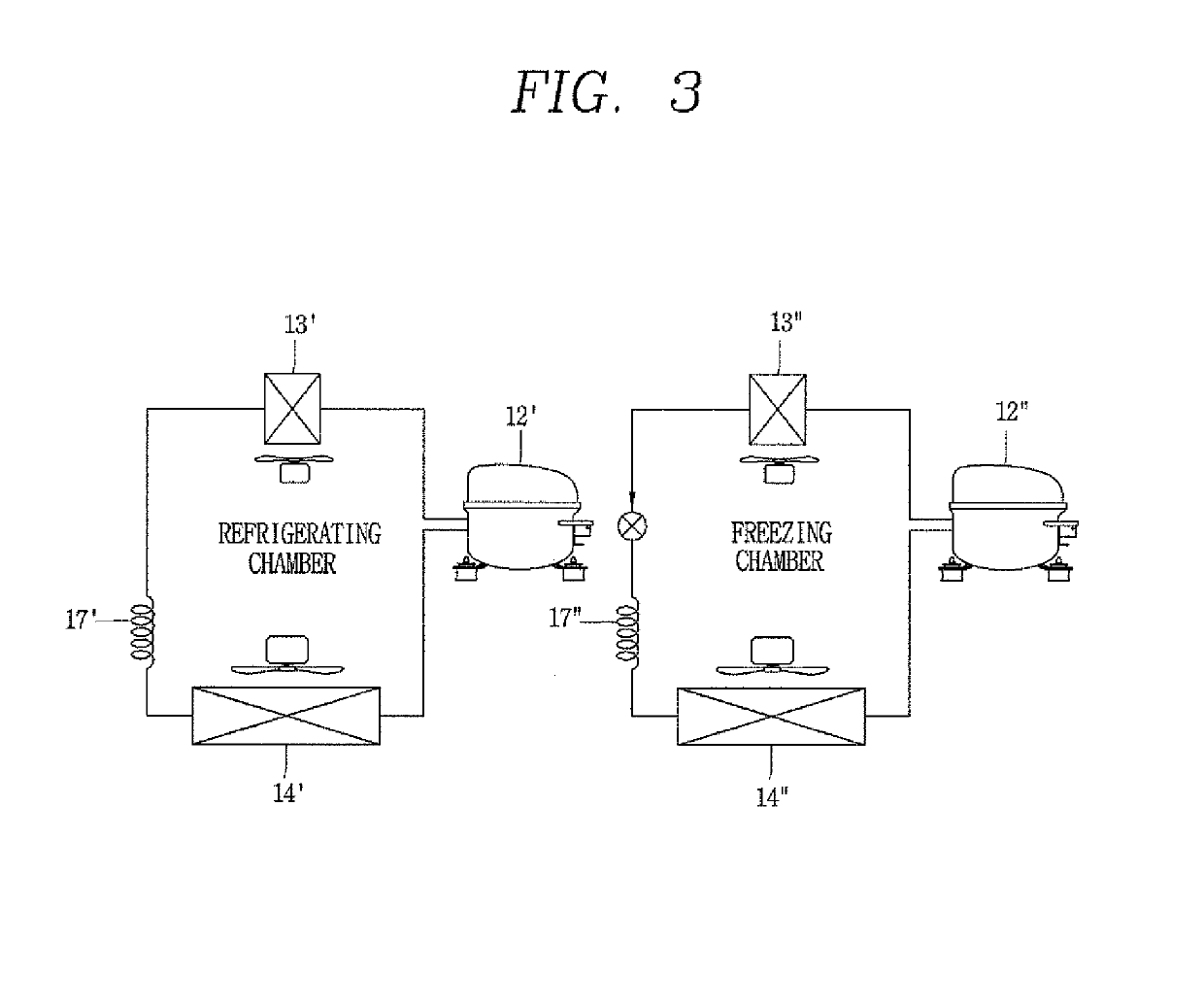
[0050]A technology disclosed in the present disclosure relates to an inverter module for driving a motor, and more particularly, an inverter module disclosed in the present disclosure may be used for a compressor or the like applicable to a refrigerator or air conditioner, but the technology disclosed in the present disclosure may be applicable to various home appliances or electronic devices in which the inverter module can be used.

[0051]In particular, an inverter module disclosed in the present disclosure is to drive a linear motor contained in a linear compressor, and two linear compressors may be independently or concurrently driven according to an operation mode through an intelligent power module (IPM) having three upper arm elements and three lower arm elements.

[0052]It should be noted that technological terms used herein are merely used to describe a specific embodiment, but not to limit the present invention. Also, unless particularly defined otherwise, technological terms ...


PUM


Abstract

The present disclosure provides an inverter module capable of driving two linear compressors through three upper arm elements and three lower arm elements. To this end, an inverter module according to an embodiment may include an inverter module including a first inverter unit including a first upper arm and a first lower arm; a second inverter unit including a second upper arm, a second lower arm, a third upper arm and a third lower arm; and a controller configured to control the switching operation of the first upper arm and the first lower arm to allow the first inverter unit to drive a first compressor in a half-bridge configuration, and control the switching operation of the second upper arm, the second lower arm, the third upper arm and the third lower arm to allow the second inverter unit to drive a second compressor in a full-bridge configuration during a first operation mode, and control the switching operation of the first upper arm, the first lower arm, the second upper arm, the second lower arm, the third upper arm and the third lower arm to allow the first inverter unit and the second inverter unit to drive the first compressor and the second compressor in a full-bridge configuration during a second operation mode.

Description

CROSS-REFERENCE TO RELATED PATENT APPLICATIONS[0001]This application is a U.S. National Stage Application under 35 U.S.C. § 371 of PCT Application No. PCT / KR2014 / 009351, filed Oct. 2, 2014, which claims priority to Korean Patent Application No. 10-2013-0118754, filed Oct. 4, 2013, whose entire disclosures are hereby incorporated by reference.TECHNICAL FIELD[0002]The present disclosure relates to an inverter module for driving a plurality of compressors and a method for controlling the same.BACKGROUND ART[0003]In general, a compressor as a device for converting mechanical energy into the compression energy of fluid is used for a portion of a refrigeration system such as a refrigerator, an air conditioner, or the like.[0004]The compressor is largely divided into a reciprocating compressor in which a compression space for inhaling or discharging a working gas is formed between a piston and a cylinder such that the piston compresses refrigerant while moving the piston in a linearly reci...

Claims


Application Information

Patent Timeline
Patent Type & Authority Patents(United States)
IPC IPC(8): F04B49/06F04B35/04F04B49/12H02M7/5387F04B15/00F04B17/03F04B19/22F25B1/02H02P25/06H02P27/06
CPCF04B49/123F04B15/00F04B17/03F04B19/22F04B35/045F25B1/02H02M7/5387H02P25/06H02P27/06F04B49/06H02P2201/05F04B2203/0402H02M1/088H02M7/493F25B49/025
Inventor HU, JINSEOKPARK, SHINHYUNPARK, GUNIL
Owner LG ELECTRONICS INC
Why Eureka
Try Eureka