Broaching cutter

a cutting blade and cutting blade technology, applied in the field of cutting blades, can solve the problems of high degree of abrasion on the first cutting blade, and achieve the effect of suppressing the occurrence of abrasion on the initial cutting blade stages

Active Publication Date: 2019-08-06
AISIN AW CO LTD
View PDF24 Cites 0 Cited by
  • Summary
  • Abstract
  • Description
  • Claims
  • Application Information

AI Technical Summary

Benefits of technology

[0005]In a conventional broach as described in Patent Document 1, however, the shape of the first cutting blade is not specifically devised. A pair of distal end corners in the first cutting blade has an obtuse angle or a right angle. The first cutting blade for rough cutting has a large cutting depth. Thus, particles of a metal constituting the broach are easily dropped off from the first cutting blade, and a high degree of abrasion thus occurs on the first cutting blade.
[0006]Preferred embodiments have been made in view of the foregoing, and is intended to provide a broaching cutter including intermediate cutting blade stages each having a curved shape or a chamfered shape to reduce a cutting depth of cutting blades in initial cutting blade stages, thereby suppressing occurrence of abrasion on the initial cutting blade stages.Means for Solving the Problem

Problems solved by technology

Thus, particles of a metal constituting the broach are easily dropped off from the first cutting blade, and a high degree of abrasion thus occurs on the first cutting blade.

Method used


Image

  • Broaching cutter
  • Broaching cutter
  • Broaching cutter

Examples


Embodiment Construction

[0036]A broaching cutter according to an embodiment will be described with reference to the drawings.

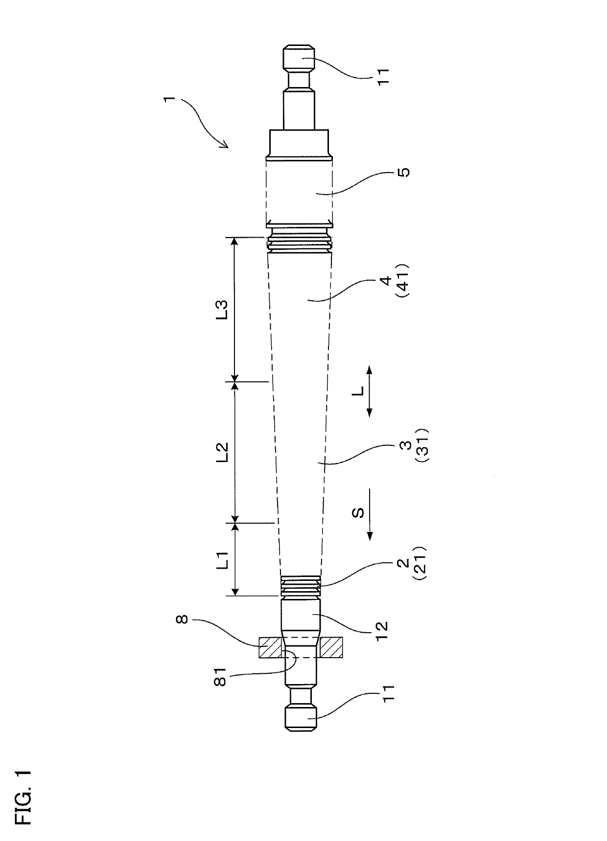
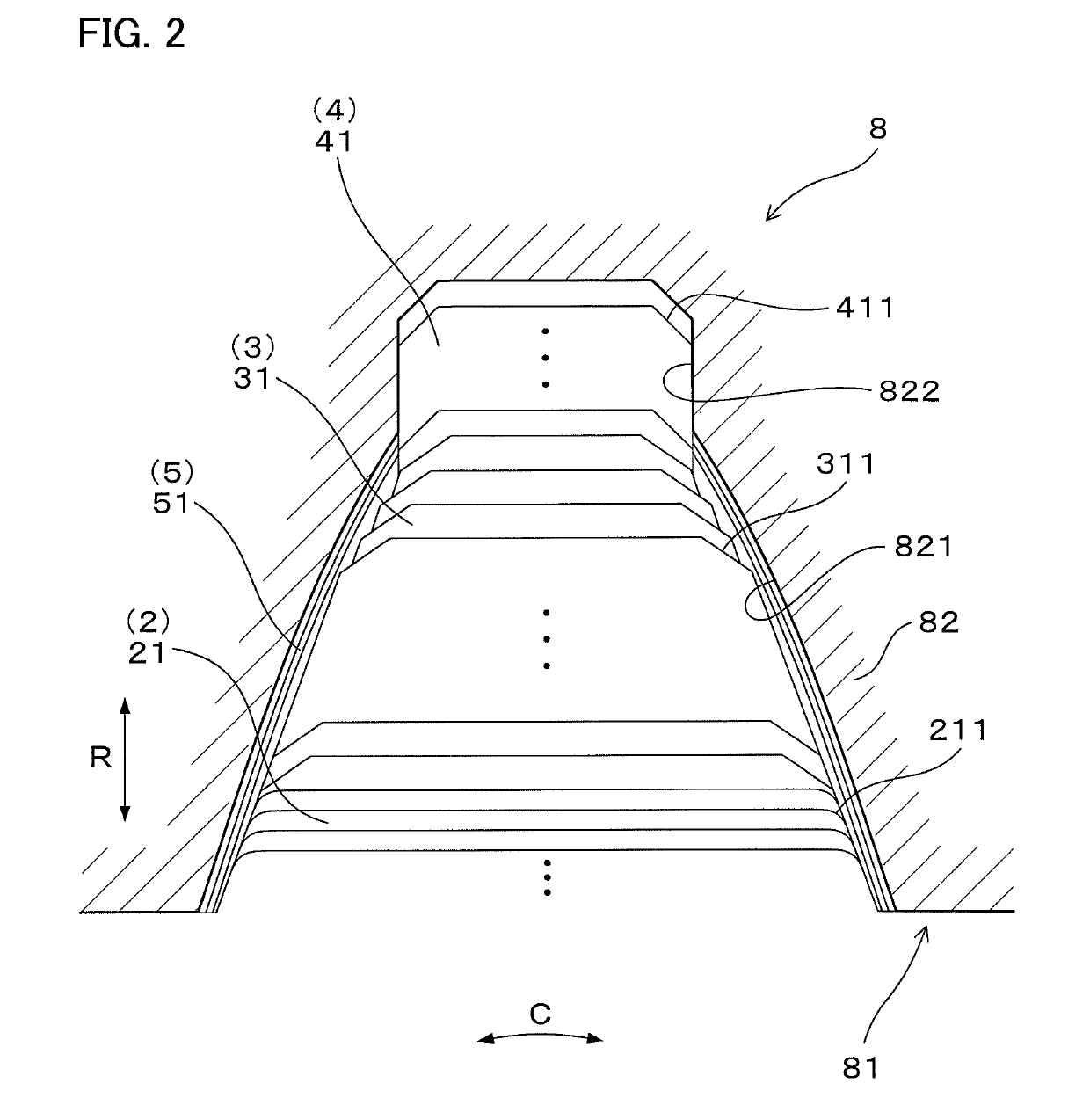
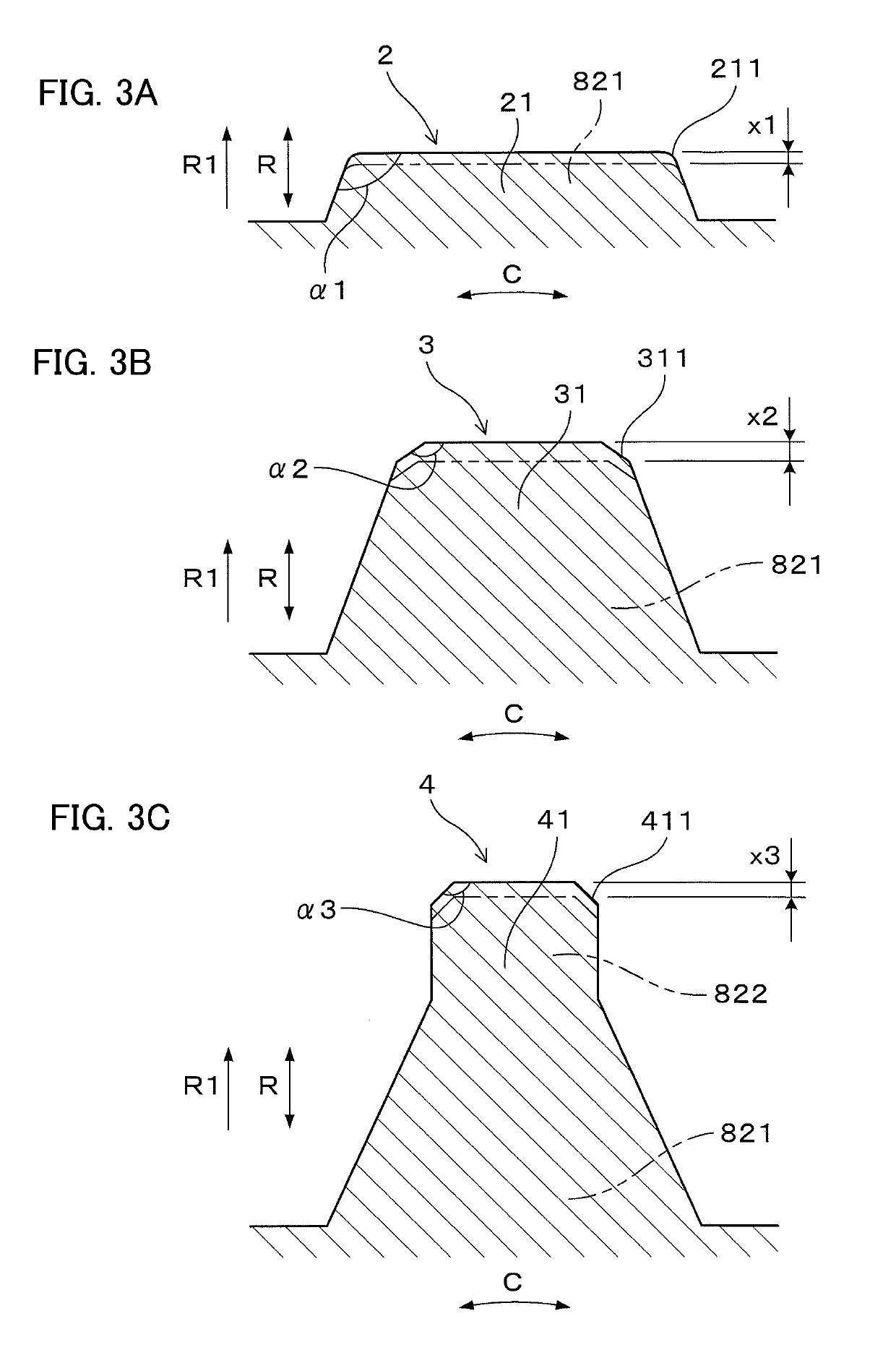
[0037]As illustrated in FIGS. 1 and 2, a broaching cutter 1 according to the present embodiment sequentially cuts a processing hole 81 in a workpiece 8 with cutting blade stages 2, 3, and 4 provided side by side in an axial direction L. The broaching cutter 1 is used for forming a plurality of internal teeth 82 in the processing hole 81 with cutting blades 21, 31, and 41 arranged side by side in a circumferential direction C of the respective cutting blade stages 2, 3, and 4 in such a manner that the internal teeth 82 are arranged side by side in the circumferential direction C. The cutting blade stages 2, 3, and 4 are configured in such a manner that cutting locations of the cutting blades 21, 31, and 41 become deeper stepwise in a radial direction R of the processing hole 81 in the workpiece 8. In the broaching cutter 1, the initial cutting blade stages 2, the intermediate cutting ...


PUM


Abstract

A broaching cutter includes a plurality of initial cutting blade stages for cutting formation portions to be tooth body portions in internal teeth, a plurality of intermediate cutting blade stages for cutting the formation portions to be the tooth body portions further deeply, and a plurality of final cutting blade stages for cutting formation portions to be clearance portions located deeper than the tooth body portions, the initial cutting blade stages, the intermediate cutting blade stages, and the final cutting blade stages being sequentially arranged from an upstream side in a cutting direction S. Each of a pair of distal end corners of each of cutting blades in the intermediate and final cutting blade stages has a chamfered shape larger than that of a curved shape of a pair of distal end corners of each of the cutting blades in the initial cutting blade stages.

Description

TECHNICAL FIELD[0001]Preferred embodiments relate to a broaching cutter for forming a plurality of internal teeth by cutting a processing hole of a workpiece.BACKGROUND ART[0002]In a broaching cutter for cutting internal teeth, a plurality of cutting blade stages each having a plurality of cutting blades arranged side by side in a circumferential direction are provided side by side in an axial direction. In the broaching cutter, a plurality of cutting blade stages for rough cutting and a plurality of cutting blade stages for finish cutting are sequentially provided side by side in a cutting direction. In the rough cutting, the cutting blades sequentially cut a processing hole in a workpiece in a radial direction to form intermediate shapes of the internal teeth. Then, in the finish cutting, the cutting blades sequentially cut the intermediate shapes of internal teeth in a circumferential direction to form the internal teeth.[0003]For example, a broach for internal teeth gear process...

Claims


Application Information

Patent Timeline
Patent Type & Authority Patents(United States)
IPC IPC(8): B23F21/26B23D43/02
CPCB23D43/02B23F21/26
Inventor YAMAYA, KENICHITANABE, MANABU
Owner AISIN AW CO LTD
Why Eureka
Try Eureka