Handheld, hand-guided cutting-off machine

a cutting-off wheel and hand-guided technology, which is applied in the direction of grinding machines, metal-working machine components, manufacturing tools, etc., can solve the problems of particularly critical support of safety guards, and achieve the effect of increasing the cutting depth of workpieces with cutting-off wheels

Inactive Publication Date: 2018-12-06
HILTI AG
View PDF41 Cites 1 Cited by
  • Summary
  • Abstract
  • Description
  • Claims
  • Application Information

AI Technical Summary

Benefits of technology

[0010]According to the present invention, the handheld, hand-guided cutting-off machine is characterized in that the pivot axis of the safety guard is displaced by a distance from the output axis of the output shaft. In a safety guard designed to be pivotable around a pivot axis, another bearing element is required for the pivotable support of the safety guard. By displacing the pivot axis with respect to the output axis, the components of the cutting-off machine situated in the area of the output shaft may be better distributed in the available space and the cutting depth thereby increased. The components situated in the area of the output shaft include a bearing for the output shaft, the safety guard, the supporting housing part and the transmission mechanism.
[0018]In one preferred refinement of the cutting-off machine according to the present invention, the flange diameter of the flange corresponds to a minimum flange diameter. The flange diameters which are specified as the lower limiting values for the flange in the particular, applicable standards are defined as minimum flange diameters. Among other things, the minimum flange diameter is dependent on the type of drive motor, the type of cutting-off wheel and the wheel diameter of the cutting-off wheel. If the flange diameter of the flange used corresponds to the minimum flange diameter, the maximum cutting depth is achievable with a cutting-off wheel, the maximum cutting depth of a cutting-off wheel being specified by half the difference between the wheel diameter of the cutting-off wheel and the minimum flange diameter. The cutting-off machine according to the present invention has the advantage that the cutting depth is increased compared to the known cutting-off machines, and the maximum cutting depth is achieved. In the cutting-off machine according to the present invention, which includes a combustion motor and a diamond cutting-off wheel, a cutting depth is achieved with a wheel diameter of 300 mm, while a diamond cutting-off wheel having a wheel diameter of 350 mm is required for known gas-powered cutting-off machines, such as the TS 400 and TS 410 cutting-off machines of the Stihl company.

Problems solved by technology

The support of the safety guard is particularly critical.

Method used


Image

  • Handheld, hand-guided cutting-off machine
  • Handheld, hand-guided cutting-off machine
  • Handheld, hand-guided cutting-off machine

Examples


Embodiment Construction

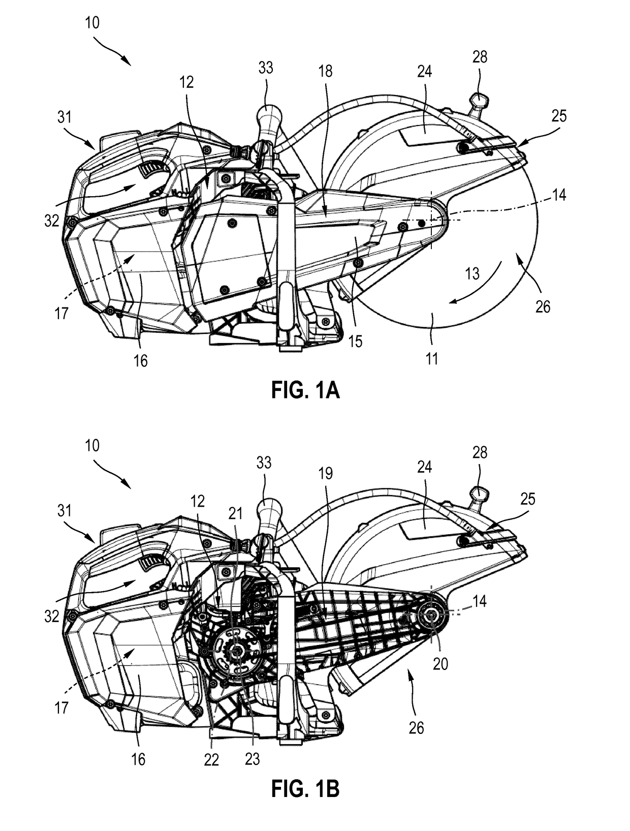
[0028]FIGS. 1A, 1B show a handheld, hand-guided power tool 10 according to the present invention, which is designed in the form of a cutting-off machine. Cutting-off machine 10 includes a machining tool designed as a cutting-off wheel 11, which is driven by a drive unit 12 in a rotation direction 13 around a rotation axis 14. All drive components for cutting-off wheel 11 are combined as drive unit 12. In cutting-off machine 10 illustrated in FIG. 1B, a cover 15 was removed, so that at least some drive components of drive unit 12 are visible. Cover 15 may have a single-part or multi-part design and is fastened to cutting-off machine 10 by screws.

[0029]Drive unit 12 includes a drive motor 17 situated in a motor housing 16, a transmission mechanism situated in a supporting arm 18 and designed as a belt drive 19, and an output shaft 20, on which cutting-off wheel 11 is mounted. Additional transmission components are connectable as needed between drive motor 17 and belt drive 19. A centr...


PUM


Abstract

A handheld, hand-guided cutting-off machine, which includes a rotating cutting-off wheel, a supporting housing part (36), an output shaft (20), which is rotatably supported around an output axis (40), a drive motor, a transmission mechanism (19), which connects the drive motor to the output shaft (20), a flange (41) and a safety guard (24), which covers the cutting-off wheel over a covering area (25). The cutting-off wheel is rotatably fixedly mounted on the output shaft (20) with the aid of the flange (41) and surrounded by the safety guard (24). The safety guard (24) is pivotable around a pivot axis, and the pivot axis is displaced by a distance from the output axis (40) of the output shaft (20).

Description

[0001]The present invention relates to an expansion dowel that includes at least one dowel body, preferably an expansion sleeve, as a first element and at least one bolt as a second element, the bolt including an expansion body, preferably an expansion cone, that pushes the dowel body radially outwardly when the expansion body is moved in an extraction direction relative to the dowel body.[0002]The present invention relates to a handheld, hand-guided cutting-off.BACKGROUND[0003]Cutting-off machines are handheld, hand-guided power tools, which include a machining tool designed in the form of a rotating cutting-off wheel. The key components of a cutting-off machine include, in addition to the cutting-off wheel, a supporting housing part, an output shaft, which is rotatably supported around an output axis, a drive motor, a transmission mechanism, which connects the drive motor to the output shaft, a flange and a safety guard, which covers the cutting-off wheel over a covering area. The...

Claims


Application Information

Patent Timeline
Patent Type & Authority Applications(United States)
IPC IPC(8): B24B55/05B23Q11/06B24B23/02B24B27/08
CPCB24B55/052B23Q11/06B24B23/02B24B27/08
Inventor GREITMANN, RALFVEIK, GUENTHERSPECHT, HELMUT
Owner HILTI AG
Why Eureka
Try Eureka