Milling cutter
a technology of cutters and cutting boards, applied in the field of milling cutters, can solve the problems of time-consuming screw use and screw exposur
- Summary
- Abstract
- Description
- Claims
- Application Information
AI Technical Summary
Benefits of technology
Problems solved by technology
Method used
Image
Examples
Embodiment Construction
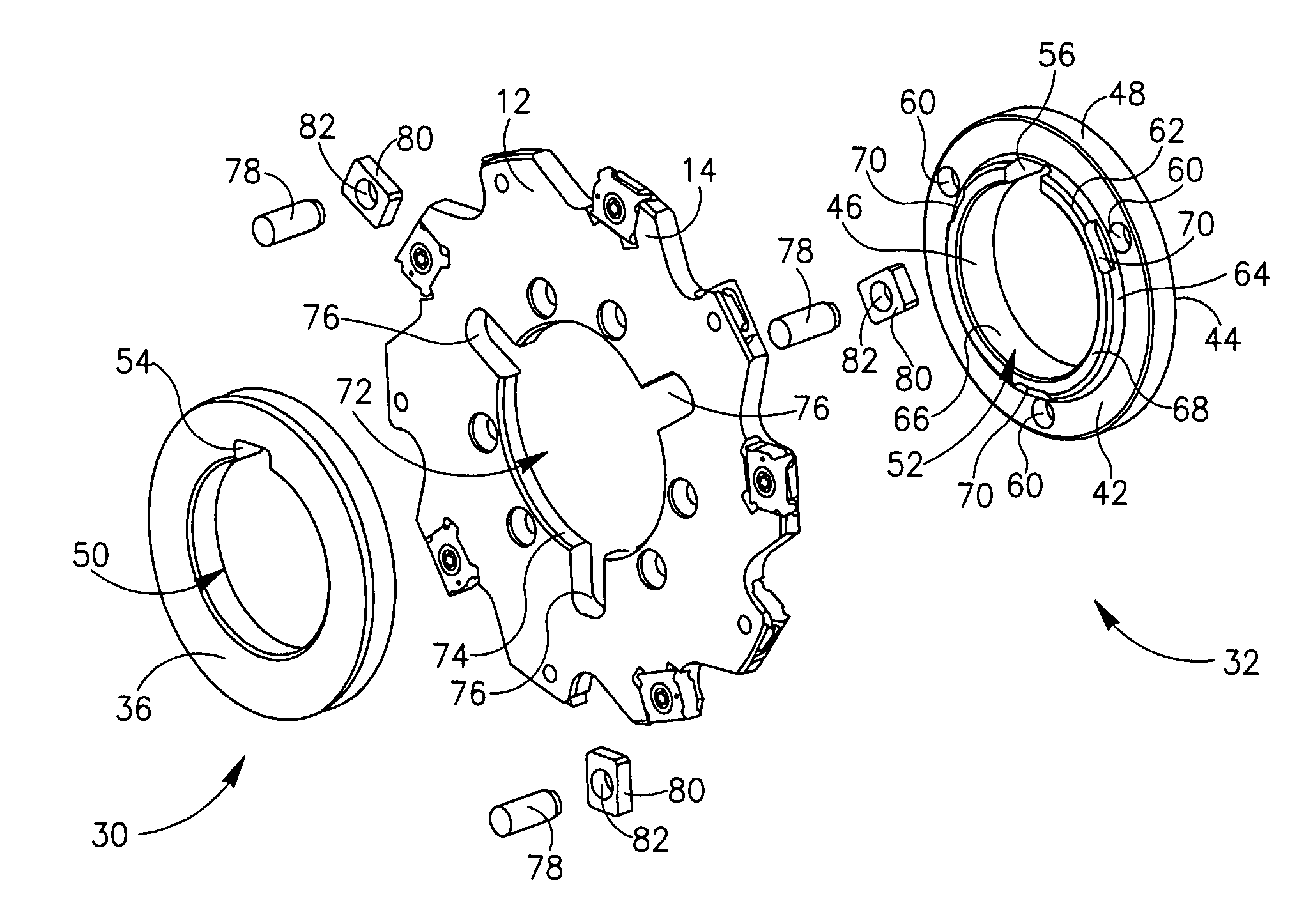
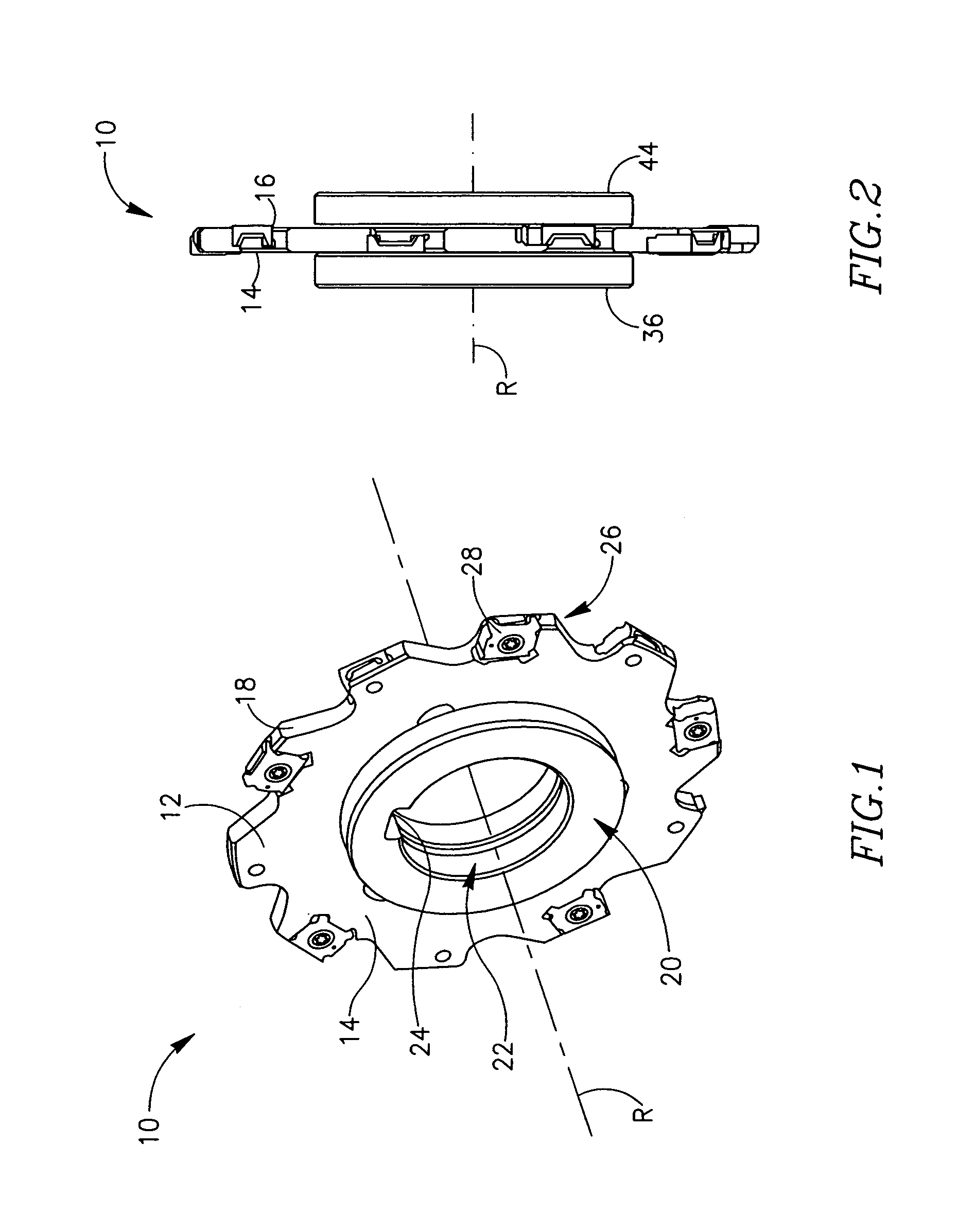
[0033] Attention is drawn to FIGS. 1 and 2, showing a milling cutter 10 in accordance with the present invention. The milling cutter 10 has a generally disk-shaped cutter body 12, having first and second opposing, generally parallel, side surfaces 14, 16 and an outer peripheral surface 18 extending between the two side surfaces 14, 16. The milling cutter 10 has an axis of rotation R which is perpendicular to the two side surfaces 14, 16. The milling cutter 10 has a hub 20 with an axially centered hole 22 for receipt of a support shaft of a machine spindle (not shown). Rotative motion is imparted to the hub 20 of the cutter via a drive key (also not shown) which mates with drive keyway 24. A plurality of circumferentially spaced apart cutting portions 26 are located around the outer peripheral surface 18 of the cutter body 12, each cutting portion 26 being provided with a cutting insert 28.
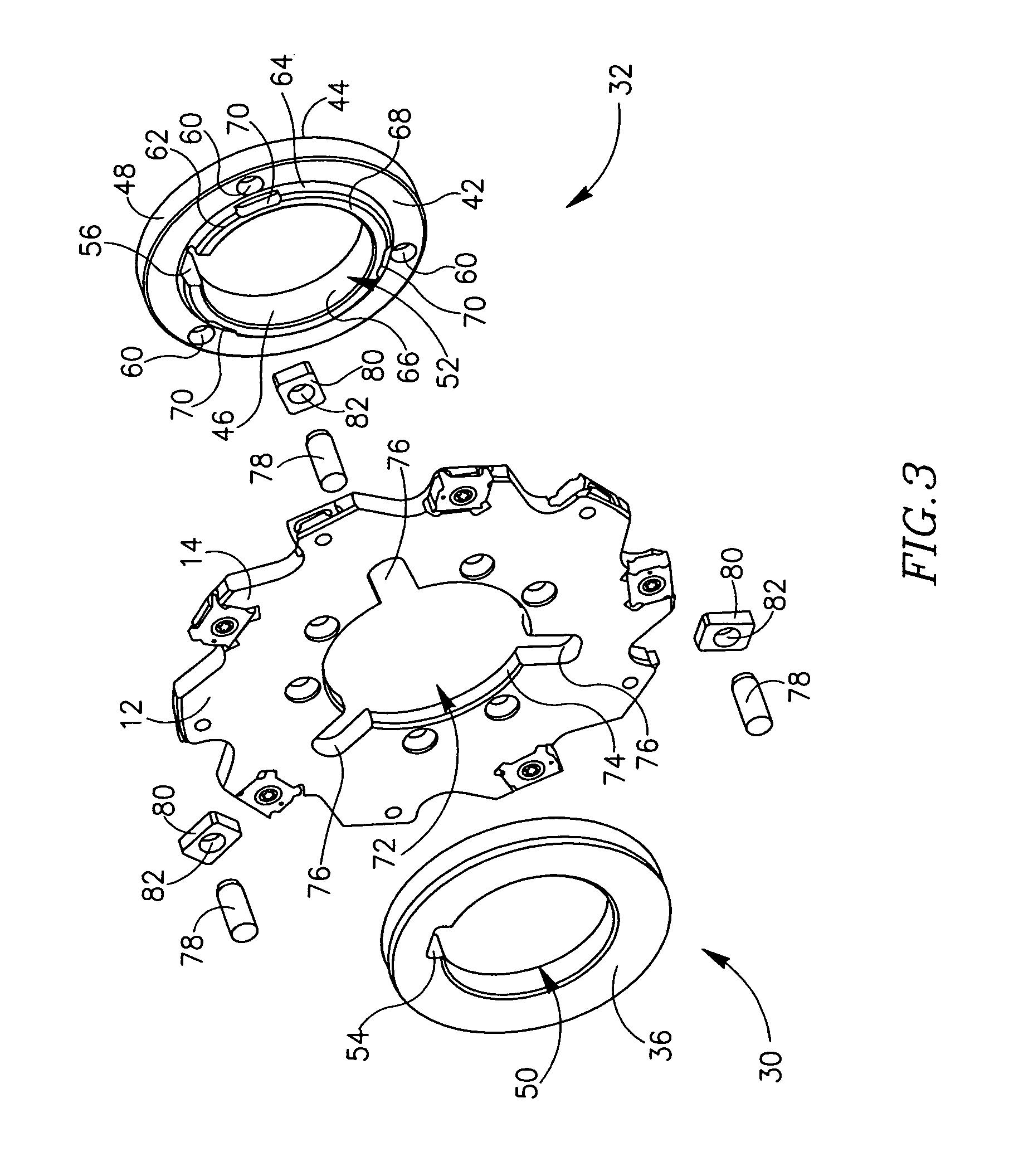
[0034] Attention is now additionally drawn to FIGS. 3 and 4. The hub 20 comprises first and se...
PUM
| Property | Measurement | Unit |
|---|---|---|
| of rotation | aaaaa | aaaaa |
| shape | aaaaa | aaaaa |
| shapes | aaaaa | aaaaa |
Abstract
Description
Claims
Application Information
 - R&D
- Intellectual Property
- Life Sciences
- Materials
- Tech Scout
- Unparalleled Data Quality
- Higher Quality Content
- 60% Fewer Hallucinations
Browse by: Latest US Patents, China's latest patents, Technical Efficacy Thesaurus, Application Domain, Technology Topic, Popular Technical Reports.
© 2025 PatSnap. All rights reserved.Legal|Privacy policy|Modern Slavery Act Transparency Statement|Sitemap|About US| Contact US: help@patsnap.com


