Eureka AIR delivers breakthrough ideas for toughest innovation challenges, trusted by R&D personnel around the world.

Connector and connector assembly

a technology of connectors and connectors, applied in the direction of coupling parts, coupling device connections, electrical apparatus, etc., can solve the problems of increasing and the contact stability of the terminals of two connectors, so as to ensure the contact stability of the terminals and reduce the height of the connector

Active Publication Date: 2019-07-23
MOLEX INC
View PDF43 Cites 1 Cited by
  • Summary
  • Abstract
  • Description
  • Claims
  • Application Information

AI Technical Summary

Benefits of technology

The patent describes a new connector and connector assembly that can maintain stable contact between terminals even if the contact area is reduced. This helps to ensure reliable communication even in smaller connectors.

Problems solved by technology

As a result, the contact stability of the terminals of two connectors is becoming a more substantial problem.

Method used


Image

  • Connector and connector assembly
  • Connector and connector assembly
  • Connector and connector assembly

Examples


Embodiment Construction

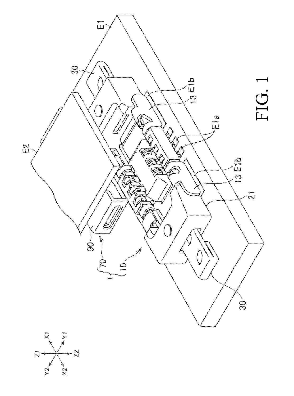
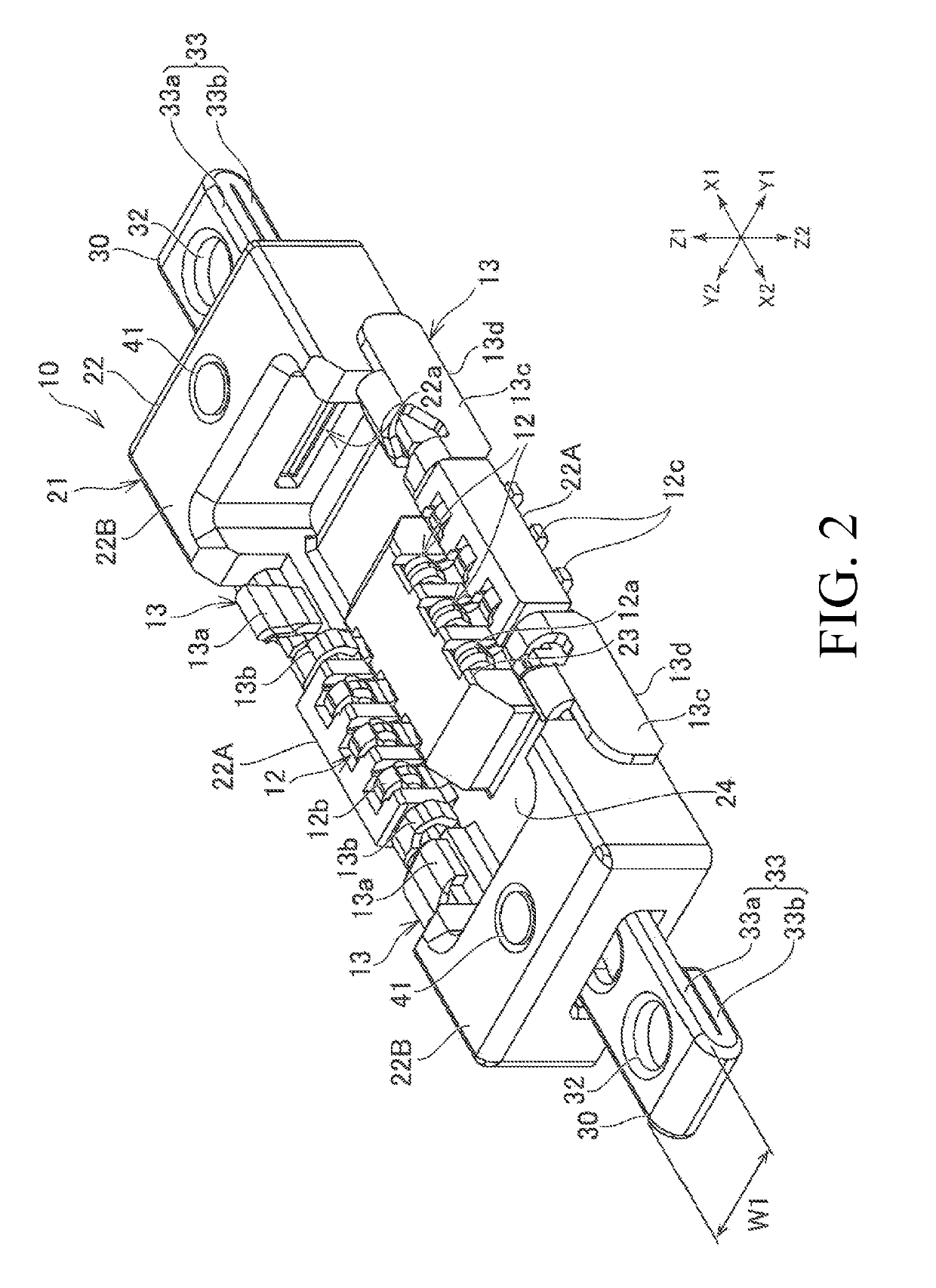
[0031]Hereinafter, embodiments of a connector and a connector assembly proposed by the present disclosure will be described. According to the present specification, as an example, a connector assembly and a connector connecting two circuit boards facing each other will be described (the term “circuit board” includes Flexible Printed Circuits (FPC) and Flexible Flat Cables (FFC)). According to the present specification, as an example of the connector assembly, a connector assembly 1 will be described. The connector assembly 1 has a first connector 10 and a second connector 70 (refer to FIG. 1).

[0032]According to the following description, the Z1 direction illustrated in FIG. 1 is referred to as the upward direction, while the Z2 direction is referred to as the downward direction. Moreover, the X1 direction and the X2 direction are respectively referred to as the right direction and the left direction, while the Y1 direction and the Y2 direction are respectively referred to as the fro...


PUM


Abstract

A through hole is formed in an end wall part of a first housing, and a slider is arranged in this through hole. The slider can be slid in the left-right direction between a locked position at which the slider is engaged with the second connector and an unlocked position at which the slider is separated from the second connector. The slider is a plate-like member arranged such that the thickness direction thereof is oriented in the height direction of the first housing.

Description

RELATED APPLICATIONS[0001]This application claims priority to Japanese Application No. 2017-076384, filed Apr. 7, 2017, which is incorporated herein by reference in its entirety.TECHNICAL FIELD[0002]The present disclosure relates to a connector and a connector assembly.BACKGROUND ART[0003]Conventionally, a connector is used to connect two circuit boards facing each other (for example, see the following patent documents 1 to 4). A connector attached to one circuit board and another connector attached to the other circuit board are fitted to each other, thereby, connecting the two circuit boards. The height of this kind of connector is being reduced in association with the advancement of miniaturized, slimmer designs of electronic devices.[0004]Patent Document 1: Japanese Unexamined Patent Application Publication No. H4-368783[0005]Patent Document 2: Japanese Unexamined Patent Application Publication No. 2014-212039[0006]Patent Document 3: Japanese Unexamined Patent Application Public...

Claims


Application Information

Patent Timeline
Patent Type & Authority Patents(United States)
IPC IPC(8): H01R13/62H01R12/71H01R13/631H01R13/639H01R13/502
CPCH01R13/639H01R13/631H01R13/502H01R12/716
Inventor NISHI, NORIHIRO
Owner MOLEX INC
Why Eureka
Eureka Blog
Learn More