Eureka AIR delivers breakthrough ideas for toughest innovation challenges, trusted by R&D personnel around the world.

MRI compatible leads for a deep brain stimulation system

a deep brain stimulation and compatible technology, applied in the field of lead for an implanted medical device, can solve the problems of large amount of energy to be absorbed in the tissue, limited compatibility of these medical devices with magnetic resonance imaging (mri), standard diagnostic tool in medicine, heat-related injury, etc., to reduce the antenna effect, reduce the effect of tissue heating during mri and limited compatibility with mri

Active Publication Date: 2019-07-02
THE GENERAL HOSPITAL CORP
View PDF3 Cites 2 Cited by
  • Summary
  • Abstract
  • Description
  • Claims
  • Application Information

AI Technical Summary

Benefits of technology

[0009]Clinical electrical stimulation systems—such as pacemakers and deep brain stimulators (DBS)—are an increasingly common therapeutic option to treat a large range of medical conditions. Despite their remarkable success, one of the significant limitations of these medical devices is the limited compatibility with magnetic resonance imaging (MRI), a standard diagnostic tool in medicine. During an MRI exam, the leads used with these devices, implanted in the body of the patient, act as an electric antenna potentially causing a large amount of energy to be absorbed in the tissue, which can lead to heat-related injury. This disclosure presents a novel lead design that reduces the antenna effect and allows for decreased tissue heating during MRI. The parameters of the lead wire design were determined by a combination of computational modeling and experimental measurements. The results of these simulations were used to build lead wires, which were tested in a gel phantom during an MRI scan. Measurement results showed a three-fold decrease in heating when compared to a commercially available DBS lead. Accordingly, the lead of the present disclosure allows a significantly increased number of patients with medical implants to have safe access to the diagnostic benefits of MRI.
[0010]The present disclosure provides a lead for an implanted medical device in which the lead is adapted for electrical communication with an electrical signal source and has a distal tip with an electrode. The lead comprises a wire adapted to be placed in electrical communication with electrode. The wire includes: (i) a core comprising a polymeric material, and (ii) a metallic layer surrounding an outer surface of the core. The metallic layer includes a first section having a first thickness and a second section having a second thickness, wherein the first thickness is greater than the second thickness. The lead is substantially transparent to radio frequency waves in clinically-applicable magnetic resonance environments to reduce radio frequency absorption and avoid substantial heating effects.
[0011]The present disclosure also provides a lead for an implanted medical device in which the lead is adapted for electrical communication with an electrical signal source and has a distal tip with an electrode. The lead comprises a wire adapted to be placed in electrical communication with electrode. The wire includes: (i) a core comprising a polymeric material, and a metallic layer surrounding an outer surface of the core, wherein the metallic layer includes a discontinuity in electrical conductivity along its axial length. The lead is substantially transparent to radio frequency waves in clinically-applicable magnetic resonance environments to reduce radio frequency absorption and avoid substantial heating effects.

Problems solved by technology

Despite their remarkable success, one of the significant limitations of these medical devices is the limited compatibility with magnetic resonance imaging (MRI), a standard diagnostic tool in medicine.
During an MRI exam, the leads used with these devices, implanted in the body of the patient, act as an electric antenna potentially causing a large amount of energy to be absorbed in the tissue, which can lead to heat-related injury.

Method used


Image

  • MRI compatible leads for a deep brain stimulation system
  • MRI compatible leads for a deep brain stimulation system
  • MRI compatible leads for a deep brain stimulation system

Examples


example 1

Methods

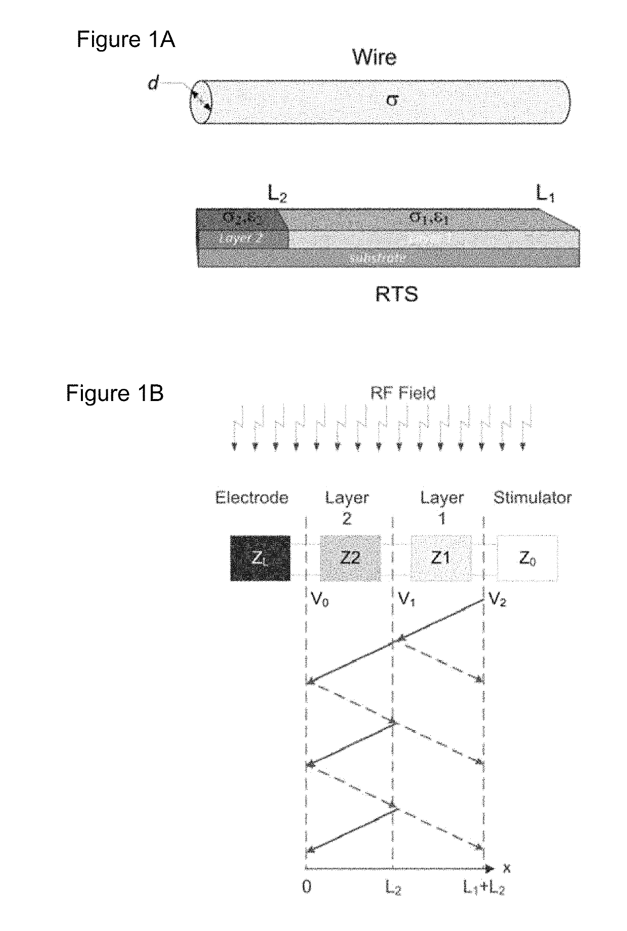
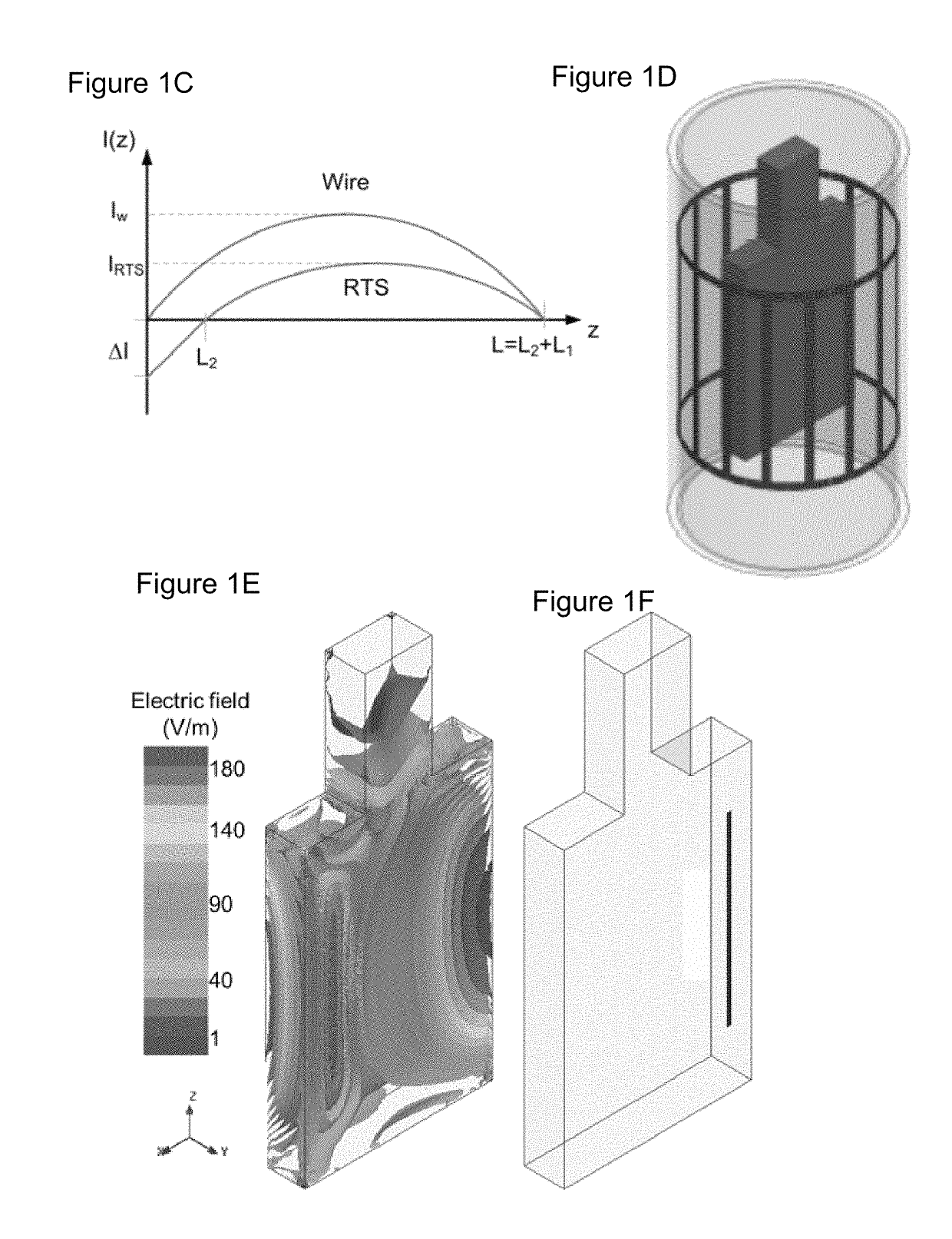
[0109]Theoretical background on RTS design. The RTS implant exposed to an RF field can be represented with a hybrid model composed of an antenna attached to a transmission line, which consists of resistive traces with sharp changes in conductivity to maximize reflections, followed by a load such as an electrode connected to the tissue (see FIG. 1a). As described in Ref. 32, the equivalent antenna (i.e., the entire RTS lead) receives the electromagnetic (EM) field and injects it into the first port (i.e., layer) with impedance Z1 of such a network (see FIG. 1b). A portion of the power transmitted to the first port of the RTS is reflected back as a result of an impedance mismatch between the first port and the antenna, while a remaining portion is supplied to the second layer of the RTS. The impedance of this second port is intentionally mismatched to reflect the greatest amount of power back to the implantable pulse generator (IPG) and away from the electrode that is in contac...


PUM


Abstract

A lead for an implanted medical device is disclosed in which the lead is adapted for electrical communication with an electrical signal source and has a distal tip with an electrode. The lead comprises a wire adapted to be placed in electrical communication with electrode. The wire includes: (i) a core comprising a polymeric material, and (ii) a metallic layer surrounding an outer surface of the core. The metallic layer includes a first section having a first thickness and a second section having a second thickness, wherein the first thickness is greater than the second thickness. The lead is substantially transparent to radio frequency waves in clinically-applicable magnetic resonance environments to reduce radio frequency absorption and avoid substantial heating effects.

Description

CROSS-REFERENCES TO RELATED APPLICATIONS[0001]This application claims priority from U.S. Patent Application No. 62 / 048,534 filed Sep. 10, 2014 and U.S. Patent Application No. 62 / 132,671 filed Mar. 13, 2015.STATEMENT REGARDING FEDERALLY SPONSORED RESEARCH[0002]This invention was made with government support under grants U01-NS075026 (NIH / NINDS), 1R21EB016449-01A1 (NIH / NIBIB), and the National Center for Research Resources (P41-RR14075). The government has certain rights in the invention.BACKGROUND OF THE INVENTION[0003]1. Field of the Invention[0004]The invention relates to a lead for an implanted medical device in which the lead includes a wire for placing an electrical signal source in electrical communication with an electrode at a distal tip of the lead. The lead is substantially transparent to radio frequency waves in clinically-applicable magnetic resonance environments to avoid radio frequency heating effects.[0005]2. Description of the Related Art[0006]Magnetic resonance imag...

Claims


Application Information

Patent Timeline
Patent Type & Authority Patents(United States)
IPC IPC(8): A61N1/05A61N1/08A61N1/37
CPCA61N1/08A61N1/0534A61N1/086A61N1/3718A61N1/0551A61N1/0563
Inventor KATNANI, HUSAMBONMASSAR, GIORGIO
Owner THE GENERAL HOSPITAL CORP
Why Eureka
Eureka Blog
Learn More