
Opto-physiological sensor and method of assembly

a sensor and optophysiological technology, applied in the field of optophysiological (op) sensors, can solve the problems of unpopular frequent use, no wearable sensor is currently available that can simultaneously measure a wider range, etc., and achieve the effect of saving energy, optimum reliability of output, and more accurate and reliabl

Active Publication Date: 2019-06-25
LOUGHBOROUGH UNIV
View PDF17 Cites 1 Cited by
  • Summary
  • Abstract
  • Description
  • Claims
  • Application Information

AI Technical Summary

Benefits of technology

The patent describes a sensor that uses multiple light sources and wavelengths to improve the accuracy and reliability of measuring opto-physiological properties of tissue. This allows for a more robust overall performance of the sensor, with a more reliable measurement of vital signs from multiple locations on the subject's tissue. The sensor is designed as an adhesive patch that is convenient and comfortable to wear. The analyser uses an opto-physiological model to interpret the optical signals and their correlation with blood volume and age, providing a more reliable interpretation of the data.

Problems solved by technology

However, these are often inaccurate as they do not take into account the light scattering effects of live tissue, motion induced artefacts or the effects of sweat, skin creams or sprays.
However, these tend to be uncomfortable and obtrusive making them unpopular for frequent use.
However, no wearable sensor is currently available that can simultaneously measure a wider range of physiological parameters, including blood oxygen saturation.

Method used


Image

  • Opto-physiological sensor and method of assembly
  • Opto-physiological sensor and method of assembly
  • Opto-physiological sensor and method of assembly

Examples


Embodiment Construction

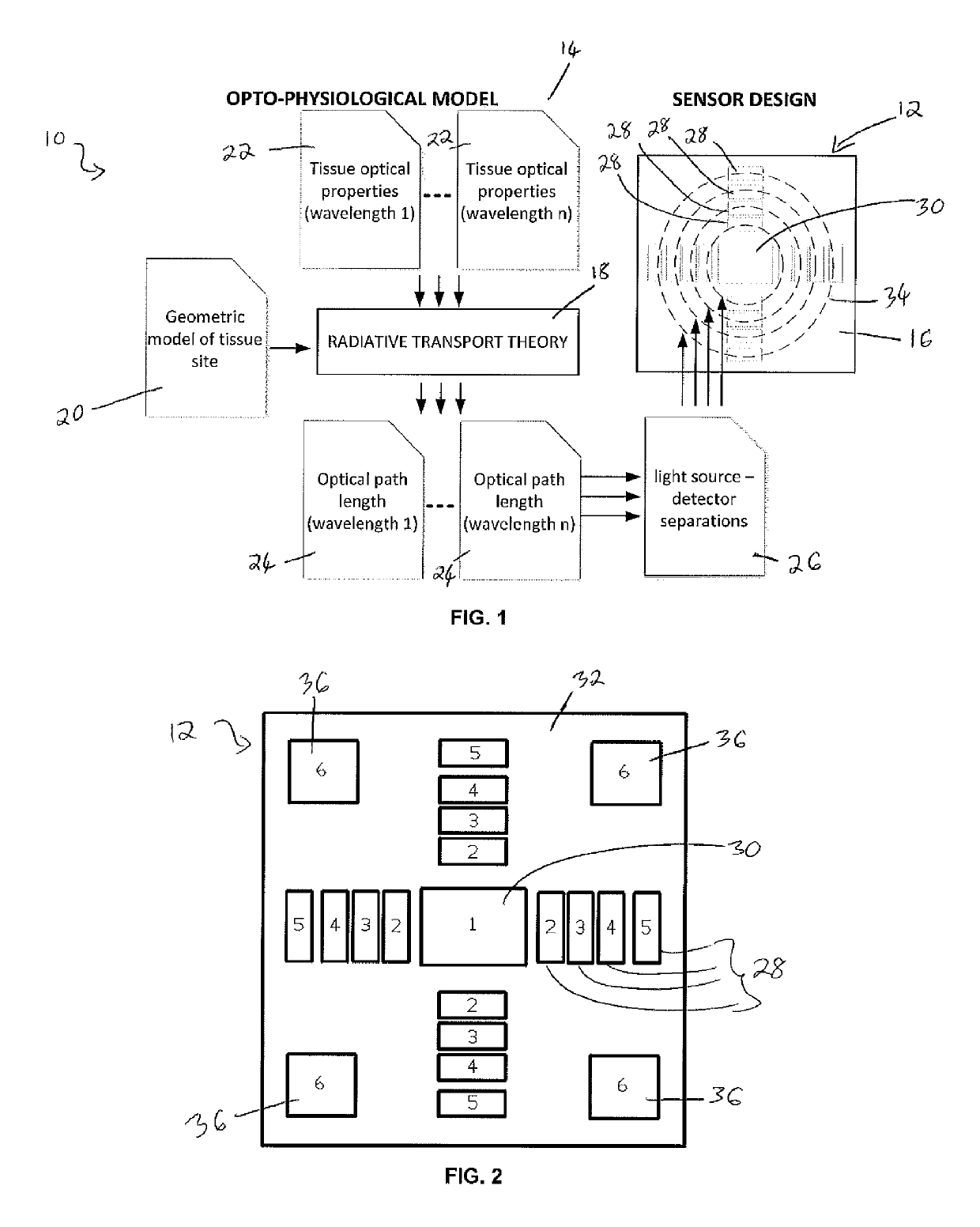
[0112]With reference to FIG. 1, there is illustrated a flow diagram 10 of a method of assembling (including designing) an opto-physiological (OP) sensor 12 in accordance with an embodiment of the present invention. The method comprises using an opto-physiological model 14 to mathematically model the opto-physiological properties of a body tissue type to be monitored and determining, through application of the model 14, an optimal optical design 16 for the opto-physiological (OP) sensor 12 so that it is operable to monitor the opto-physiological properties of the body tissue type. Thus, an aspect of the invention relates to a data-driven design approach for an optical sensing sub-system. Furthermore, the method includes making the OP sensor 12 to the determined optical design wherein the optimal optical design for the OP sensor 12 comprises: (i) determining the optimum separation of each of a plurality of light sources 28 from a photodetector 30, based on modelled optical path length...


PUM


Abstract

A method of assembling an opto-physiological (OP) sensor comprises: (i) modelling the opto-physiological properties of at least one body tissue type to be monitored; (ii) determining, through application of the model, an optimal optical design for an opto-physiological (OP) sensor operable to monitor the opto-physiological properties of the at least one body tissue type; and (iii) making the OP sensor to the determined optical design. The optimal optical design for the OP sensor comprises: (i) determining the optimum separation of each of a plurality of light sources from a photodetector, based on modelled optical path lengths for light travelling from each light source, through the body tissue type to be monitored, to the photodetector; and (ii) locating light sources of different wavelengths at different distances from the photodetector.

Description

FIELD OF THE INVENTION[0001]The present invention relates to an opto-physiological (OP) sensor and a method of assembling such a sensor. Aspects of the invention also relate to a physiological sensor system comprising the OP sensor and, in particular, to the geometrical distribution of associated illumination sources.BACKGROUND TO THE INVENTION[0002]Photoplethysmography (PPG) is a non-invasive optical technique for monitoring variation in blood volume or blood flow near the surface of the skin to determine various physiological parameters. The principle uses an illumination source and a photodetector to measure changes in intensity as light is passed through or reflected from body tissue. The detected optical signals are then analysed and correlated with the pulsation of blood through the body, as stimulated by the heartbeat. More background information about PPG can be found in the topical review “Photoplethysmography and its application in clinical physiological measurement”, John...

Claims


Application Information

Patent Timeline
Patent Type & Authority Patents(United States)
IPC IPC(8): A61B5/00A61B5/01A61B5/1455A61B5/11A61B5/024A61B5/021G16H50/50A61B5/08
CPCA61B5/7475A61B5/742A61B5/02427A61B5/0015A61B5/01A61B5/11A61B5/14552A61B5/7225A61B5/021A61B5/02405A61B5/0816A61B5/7203A61B5/7221A61B2560/0223A61B2562/0242A61B2562/12G16H50/50A61B5/0002A61B5/0059A61B5/0261A61B5/1455A61B5/1032A61B5/14551A61B5/441A61B5/7214G06F30/00
Inventor HU, SIJUNGAZORIN-PERIS, VICENTE
Owner LOUGHBOROUGH UNIV
Learn More