Solid electrolytic capacitor including a flat plate anode wire and an anode terminal with a mounting portion and an upright portion
a solid electrolytic capacitor and anode terminal technology, applied in capacitors, capacitor housing/encapsulation, basic electric elements, etc., can solve the problem of self-alignment property degrading to a board to be soldered, and achieve the effect of sufficient welding strength
- Summary
- Abstract
- Description
- Claims
- Application Information
AI Technical Summary
Benefits of technology
Problems solved by technology
Method used
Image
Examples
first embodiment
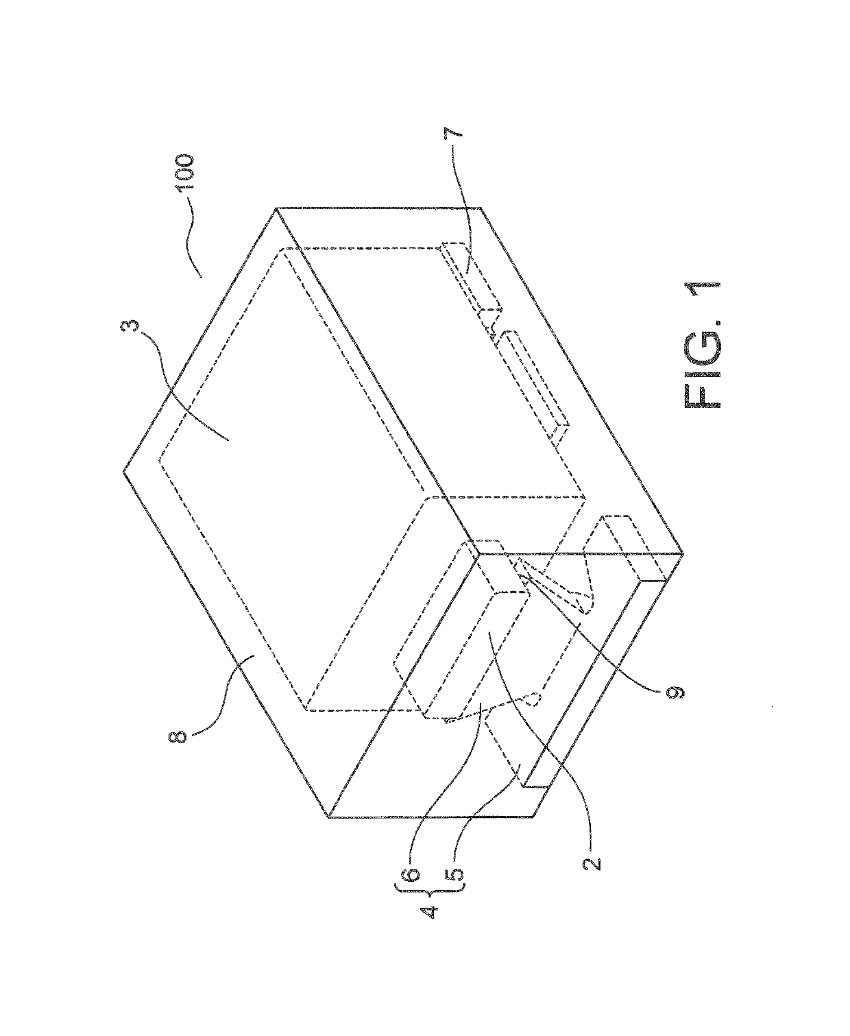
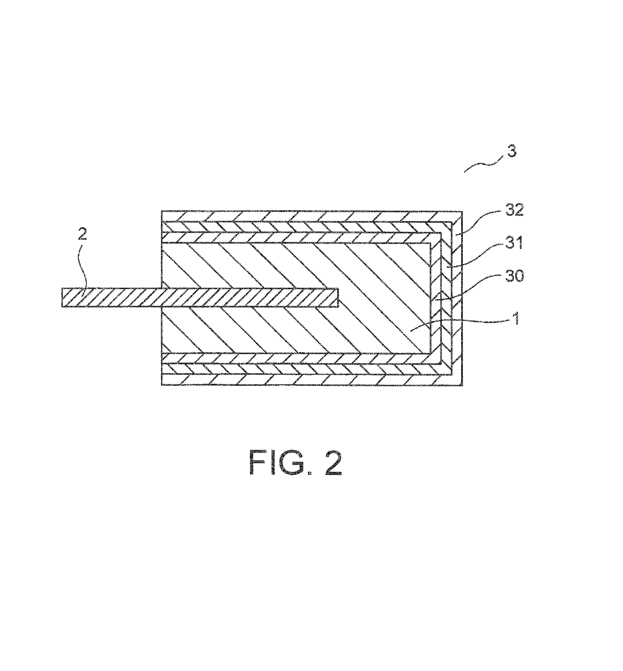
[0024]FIG. 1 is a perspective view for illustrating a solid electrolytic capacitor according to a first embodiment of this invention. The solid electrolytic capacitor according to the first embodiment of this invention is described with reference to FIGS. 1 and 2. As illustrated in FIG. 1, a solid electrolytic capacitor 100 of this embodiment includes a capacitor element 3, an anode terminal 4, a cathode terminal 7, and an exterior resin 8. In FIG. 2, the capacitor element 3 has an anode body 1, or a sintered compact 1 of valve action metal powder, which anode body or compact serves as an anode. The capacitor element 3 has a flat plate-like anode wire 2 delivered from the anode body 1.
[0025]Over a surface of the sintered compact 1 obtained by molding valve action metal powder and sintering the resultant at high temperature, there are formed sequentially a dielectric layer 30 including an oxide film and the like, an electrolyte layer 31 including a conductive polymer layer and the li...
second embodiment
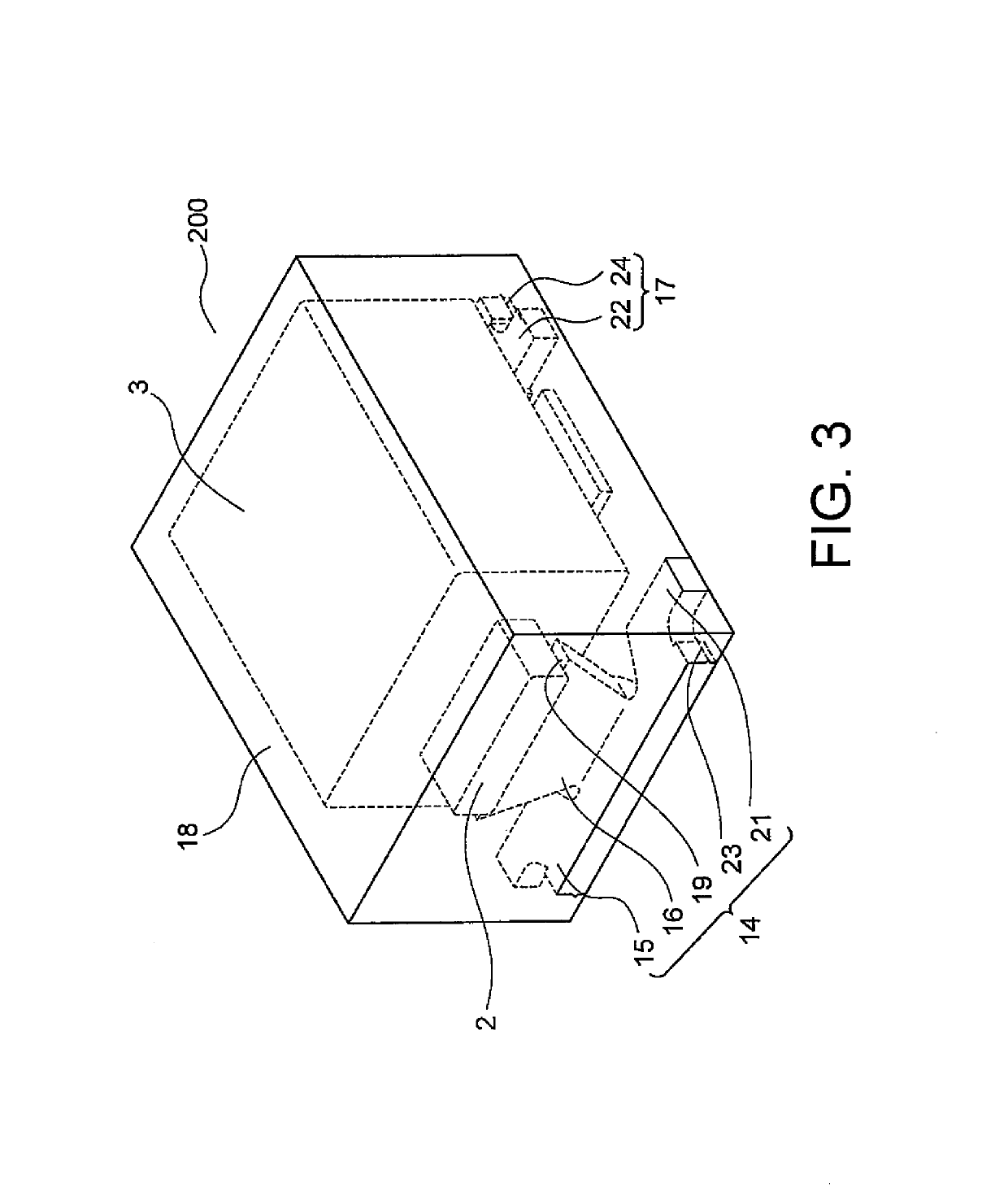
[0033]FIG. 3 is a perspective view for illustrating a solid electrolytic capacitor according to a second embodiment of this invention. The solid electrolytic capacitor according to the second embodiment of this invention is described with reference to FIG. 3. As illustrated in FIG. 3, a solid electrolytic capacitor 200 of this embodiment includes, a capacitor element 3, an anode terminal 14, a cathode terminal 17, and an exterior resin 18. As the capacitor element, the one as shown in FIG. 2 is used. That is, the capacitor element 3 has an anode body 1, or a sintered compact 1, of valve action metal powder, which anode body or compact serves as an anode. The capacitor element 3 has a flat plate-like anode wire 2 delivered from the anode body 1.
[0034]Over a surface of the sintered compact 1 obtained by molding valve action metal powder and sintering the resultant at high temperature, there are formed sequentially a dielectric layer 30 including an oxide film and the like, an electrol...
third embodiment
[0045]A solid electrolytic capacitor according to a third embodiment of this invention includes a capacitor element, an anode terminal, a cathode terminal, and an exterior resin. The capacitor element has an anode body, or a sintered compact of valve action metal powder, which anode body or compact serves as an anode. The capacitor element has a circular anode wire delivered from the anode body.
[0046]The anode terminal has a mounting portion and an upright portion that is raised from the mounting portion toward the anode wire of the capacitor element. In this case, the upright portion is connected to the mounting portion by welding. In other words, the anode terminal is formed by connecting the upright portion and the mounting portion to each other by welding, which are different members.
[0047]The upright portion has a main surface and side surfaces. The upright portion has a surface, opposed to the main surface, which has the same shape as the main surface. A length of an edge of t...
PUM
| Property | Measurement | Unit |
|---|---|---|
| width | aaaaa | aaaaa |
| thickness | aaaaa | aaaaa |
| length | aaaaa | aaaaa |
Abstract
Description
Claims
Application Information
 - R&D
- Intellectual Property
- Life Sciences
- Materials
- Tech Scout
- Unparalleled Data Quality
- Higher Quality Content
- 60% Fewer Hallucinations
Browse by: Latest US Patents, China's latest patents, Technical Efficacy Thesaurus, Application Domain, Technology Topic, Popular Technical Reports.
© 2025 PatSnap. All rights reserved.Legal|Privacy policy|Modern Slavery Act Transparency Statement|Sitemap|About US| Contact US: help@patsnap.com


