
Load control system having a visible light sensor

a technology of a control system, which is applied in the field of load control systems having a visible light sensor, can solve the problems of affecting the safety of users, so as to protect the privacy of the occupants

Active Publication Date: 2019-04-16
LUTRON TECH CO LLC
View PDF68 Cites 25 Cited by
  • Summary
  • Abstract
  • Description
  • Claims
  • Application Information

AI Technical Summary

Benefits of technology

The patent text describes how to install a visible light sensor in a space to record images without compromising the privacy of the space's occupants. The sensor can also communicate with other devices using a secure network. The technical effect is to provide a means for surveillance without invasion of privacy.

Problems solved by technology

Additionally, many of these devices communicate wirelessly over the same wireless communication network, which may create congestion on the network due to the number of devices that may be communicating at the same time.
The input devices in current load control systems may also be inefficient for performing their independent functions in the load control systems.
Attempting to reduce or eliminate the amount of glare within the user environment using these prediction algorithms may be unreliable.
The daylight sensors and the color temperature sensors in the load control systems may also be inefficient for gathering accurate information for performing load control.
As the occupancy / vacancy sensor generally senses the presence or absence of a person within the user environment using passive infra-red (PIR) technology, the occupancy / vacancy sensor may fail to detect the occupancy of a room due to the lack of movement by a user.
The occupancy / vacancy sensor may detect the presence or absence of a user within the user environment, but the sensor may fail to provide accurate results.
For example, the occupancy / vacancy sensor may detect other heat sources within a user environment and inaccurately determine that the heat sources are emanating from a person.
Further, the occupancy / vacancy sensor is unable to identify a person that is not moving, or that is making minor movements, within the user environment.

Method used


Image

  • Load control system having a visible light sensor
  • Load control system having a visible light sensor
  • Load control system having a visible light sensor

Examples


Embodiment Construction

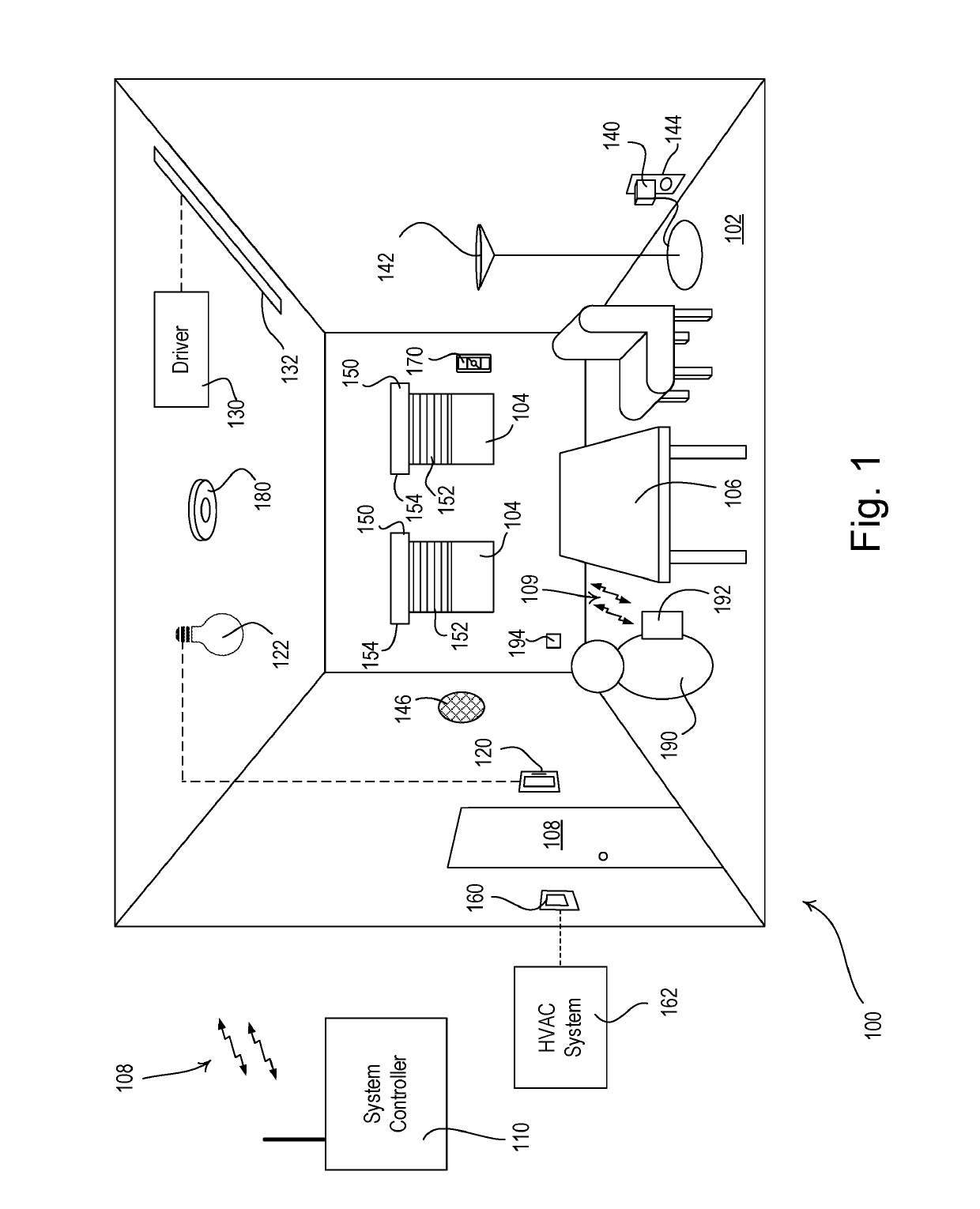
[0030]FIG. 1 is a simple diagram of an example load control system 100 for controlling the amount of power delivered from an alternating-current (AC) power source (not shown) to one or more electrical loads. The load control system 100 may be installed in a room 102 of a building. The load control system 100 may comprise a plurality of control devices configured to communicate with each other via wireless signals, e.g., radio-frequency (RF) signals 108. Alternatively or additionally, the load control system 100 may comprise a wired digital communication link coupled to one or more of the control devices to provide for communication between the load control devices. The control devices of the load control system 100 may comprise a number of control-source devices (e.g., input devices operable to transmit digital messages in response to user inputs, occupancy / vacancy conditions, changes in measured light intensity, etc.) and a number of control-target devices (e.g., load control devic...


PUM


Abstract

A sensor for sensing environmental characteristics of a space may include a visible light sensing circuit for recording an image of the space and a control circuit responsive to the visible light sensing circuit. The control circuit may detect an occupancy or vacancy condition in the space in response to the visible light sensing circuit, and measure a light level in the space in response to the visible light sensing circuit. The control circuit may also include a low-energy occupancy sensing circuit for detecting an occupancy condition in the space. The control circuit may disable the visible light sensing circuit when the space is vacant. The control circuit may detect an occupancy condition in the space in response to the low-energy occupancy sensing circuit and subsequently enable the visible light sensing circuit. The visible light sensor may be configured in a way that protects the privacy of the occupants of the space.

Description

CROSS-REFERENCE TO RELATED APPLICATIONS[0001]This application claims the benefit of U.S. Provisional Patent Application No. 62 / 266,370, filed Dec. 11, 2015, the entire disclosure of which is incorporated by reference herein.BACKGROUND[0002]A user environment, such as a residence or an office building, for example, may be configured using various types of load control systems. A lighting control system may be used to control the lighting loads providing artificial light in the user environment. A motorized window treatment control system may be used to control the natural light provided to the user environment. An HVAC system may be used to control the temperature in the user environment.[0003]Each load control system may include various control devices, including input devices and load control devices. The load control devices may receive digital messages, which may include load control instructions, for controlling an electrical load from one or more of the input devices. The load ...

Claims


Application Information

Patent Timeline
Patent Type & Authority Patents(United States)
IPC IPC(8): H05B37/02G05B19/048H04N5/232G06K9/46G06K9/00H04N7/18
CPCH05B37/0218G05B19/048G06K9/00335G06K9/4652G06K9/4671H04N5/232H04N7/188H05B37/0227H05B37/0254H05B37/0272H04N5/23212G06K2009/4666G05B2219/23153H05B47/105H05B47/19H05B47/125Y02B20/40H05B47/11H05B47/18H05B47/115G06V40/20
Inventor STEINER, JAMES P.
Owner LUTRON TECH CO LLC
Learn More