
Fluidically sealed enclosure for window electrical connections

a technology for electrical connections and enclosures, applied in the direction of electrical apparatus casings/cabinets/drawers, coupling device connections, casings/cabinets/drawers details, etc., can solve the problems of easy cracking of glass panes, failure of solder joints, and prone to mechanical stress on solder joints, so as to reduce mechanical stress, reduce water ingress, and reduce the effect of eliminating drawbacks

Active Publication Date: 2019-04-16
AGC AUTOMOTIVE AMERICAS CO A DIV OF AGC FLAT GLASS NORTH AMERICA INC
View PDF163 Cites 0 Cited by
  • Summary
  • Abstract
  • Description
  • Claims
  • Application Information

AI Technical Summary

Benefits of technology

This patent is about a window assembly that reduces mechanical stress and prevents water from getting into the electrical joints. The assembly includes a fluidically sealed enclosure that reduces stress on the components, and the fluidic seal prevents water from causing corrosion. The technical effects of this assembly are improved durability and reliability of the window assembly, especially in high-stress environments such as marine environments.

Problems solved by technology

This exposure produces corrosion, weakening, and failure of the solder joint, which prevents power from being transferred to the electrical conductor through the solder joint.
One drawback of the polymeric encapsulation includes creating mechanical stresses on the solder joint.
When the transparent pane is a glass pane, the glass pane is prone to cracking.
The mechanical stress may also delaminate the electrical conductor from the transparent pane, separate the solder joint from electrical connection with a portion of the electrical conductor, or crack the solder joint.
Another drawback of the polymeric encapsulation includes exposure of the solder joint to the elements.
As such, the water may corrode the electrical conductor or the solder joint, thereby degrading performance of the electrical conductor or rendering the electrical conductor inoperable.

Method used


Image

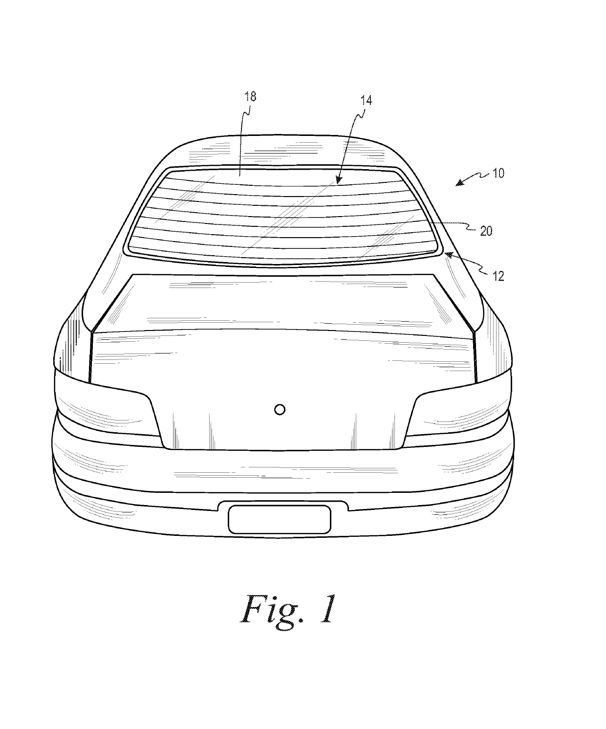
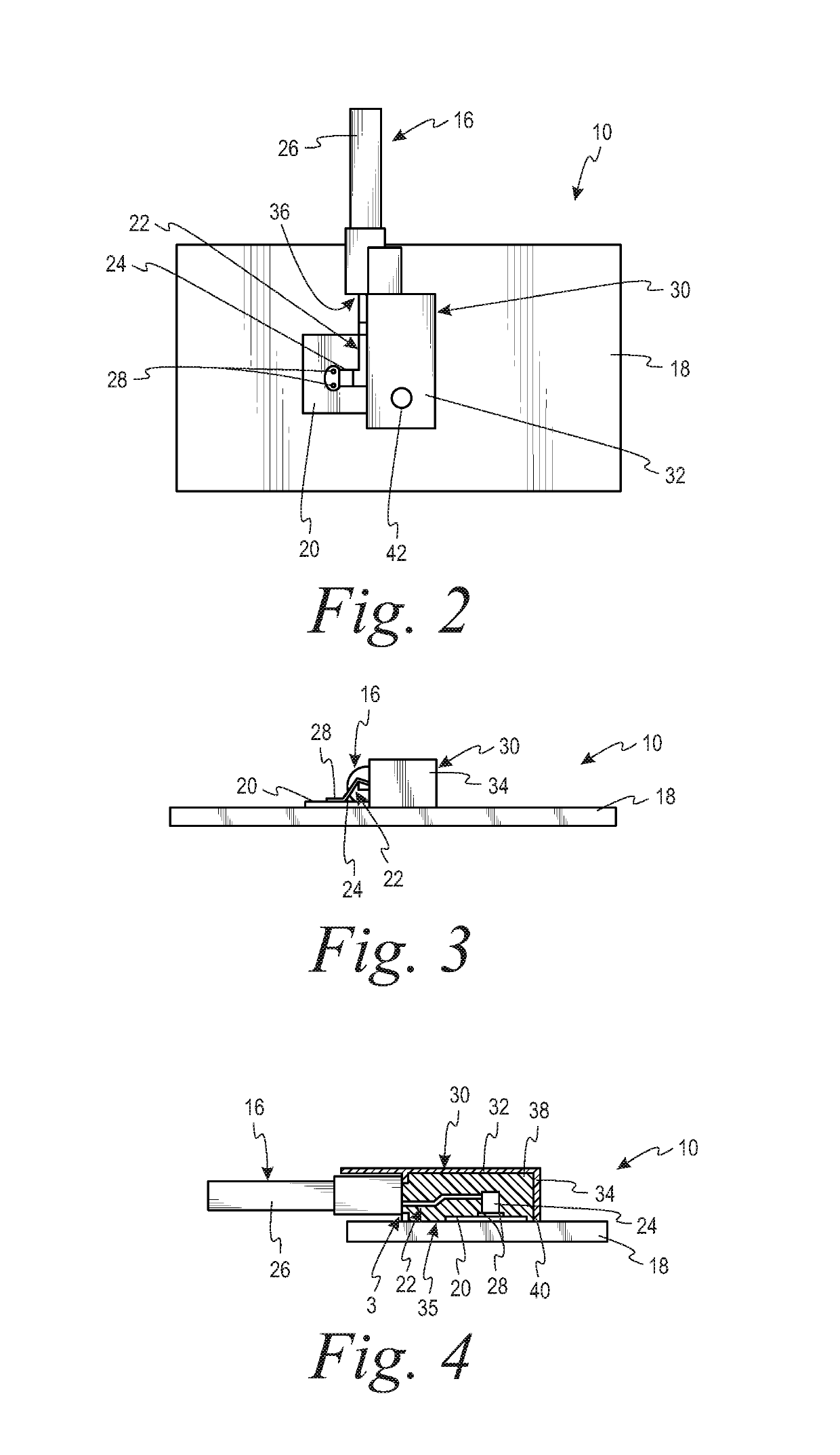
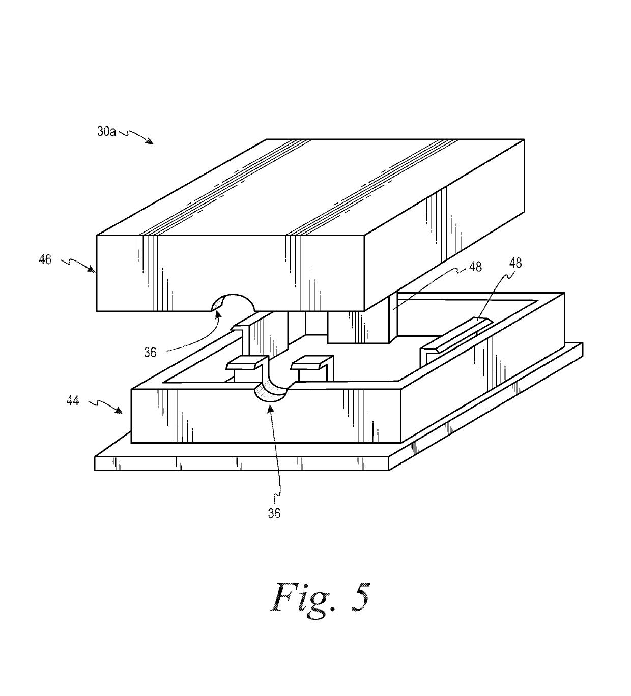
  • Fluidically sealed enclosure for window electrical connections
  • Fluidically sealed enclosure for window electrical connections
  • Fluidically sealed enclosure for window electrical connections

Examples


example 1

[0064]A sample is prepared without a mechanically protective enclosure or sealing material around an electrical joint. The sample includes a transparent pane of glass and an electrical conductor consisting essentially of silver. The electrical joint is formed on the electrical conductor. The sample is exposed to water having a 5% concentration of salt at 38° C. for 96 hours. Following the exposure, mild delamination of the electrical conductor from the glass is observed, with corrosion present on the electrical conductor proximate to the delamination site.

example 2

[0065]A sample is prepared without a mechanically protective enclosure or sealing material around an electrical joint. The sample includes a transparent pane of glass and an electrical conductor consisting essentially of silver. The electrical joint is formed on the electrical conductor. The sample is exposed to water at 50° C. for 720 hours. Following the exposure, significant delamination and peel of the electrical conductor from the glass is observed, with corrosion present on the electrical conductor proximate to the delamination site.

example 3

[0066]A window assembly is prepared with a mechanically protective enclosure around an electrical joint. No sealing material is disposed within the internal volume of the enclosure. The window assembly includes a transparent pane of glass and an electrical conductor consisting essentially of silver. The electrical joint is formed on the electrical conductor. The window assembly is exposed to field conditions for between 12 and 18 months. Following the exposure, corrosion is observed on the electrical conductor only at the contact area between the electrical conductor and the electrical joint. The corrosion covered more than 30% of the contact area.


PUM


Abstract

According to aspects of the present disclosure, a method of environmentally sealing an electrical joint formed between an electrical connection element and an electrical conductor disposed on a transparent pane is described. The method includes adhering a mechanically protective enclosure to the transparent pane to define an internal volume therebetween and filling at least a portion of the internal volume with a sealing material that inhibits ingress of liquid into the volume and provides a fluidic environmental barrier about the electrical joint. The electrical joint is disposed within the internal volume and spaced from the enclosure.

Description

INTRODUCTION[0001]The disclosure relates to the field of window assemblies, and, more specifically, to fluidically sealed enclosures for window electrical connections.[0002]Window assemblies used in, for example, vehicles and buildings can be functionalized to include an electrical conductor disposed on a surface of a transparent pane. The electrical conductor can provide any desirable electrical function such as heating the transparent pane or acting as an antenna. The electrical conductor can be, for example, a printed silver circuit. Power can be transferred from a power source to the electrical conductor through a wiring harness coupled to the electrical conductor. The wiring harness includes an electrical connection element bonded to the electrical conductor. The terminal can be bonded to the electrical conductor using an electrically conductive joint such as a solder joint.[0003]Because of their use in vehicles and buildings, the electrically conductive joint can be exposed to...

Claims


Application Information

Patent Timeline
Patent Type & Authority Patents(United States)
IPC IPC(8): H01R13/58H01R13/506H01R4/02H05K5/06H01R13/52H05K5/02H01R12/63B60J10/70
CPCH01R13/5845H01R4/023H01R13/506H01R13/5216H05K5/0247H05K5/064H05K5/0213H01R12/63B60J10/70B60R16/0215H01R13/52H01R13/5213H01R43/005H01R2201/26
Inventor IMESON, CHRISTOPHER A.SCHUCH, WILLIAM C.
Owner AGC AUTOMOTIVE AMERICAS CO A DIV OF AGC FLAT GLASS NORTH AMERICA INC
Learn More