
Lighting device, lens and method, having a mixing structure with a variable blurring strength

a mixing structure and light source technology, applied in the field of light source devices, can solve the problems of reducing the sharp cut-off of the beam edge, limiting the beam width control range of the lighting device, etc., and achieve the effects of reducing optical aberration, broadening the incoming beam, and increasing vagueness

Active Publication Date: 2019-04-02
SIGNIFY HLDG BV
View PDF7 Cites 1 Cited by
  • Summary
  • Abstract
  • Description
  • Claims
  • Application Information

AI Technical Summary

Benefits of technology

[0014]The lens can, for example, be a refractive aspheric, spherical, hyperbolic, convex-concave, plano-convex, or double convex lens. A positive lens generally redirects, converges and / or collimates light into a relatively narrow beam. Chromatic aberrations are caused by differences in refraction index for different wavelengths. The lens material can, for example be selected from soft glass, hard glass, quartz glass, or a polymeric material like PMMA, polycarbonate or polyethylene, though other (co)polymers may also be possible. Glass lenses generally can somewhat better withstand high temperatures, for example caused by the light source, but, on the other hand synthetic lenses are somewhat lighter (in weight) than glass lenses.
[0031]An embodiment of the lighting device is characterized in that the lens has diameter DL and the light source has a diameter DLS, wherein DL / DLS>=6, preferably DL / DLS>=8. For DL / DLS>=6 the light source then has a relatively small size compared to the lens that it can more or less be considered a point-like light source and imaging of the light source in the projected beam can be sufficiently be avoided. When the DL / DLS>=8 even better results are obtained as imaging of the light source in the projected beam can essentially be completely made invisible to humans. This invention can be used for a variety of light sources as known from use in spot luminaires, for example halogen lamps, high pressure gas discharge lamps (HID) and LED. The advantage of an LED is that it usually starts with a Lambertian emission pattern of about 120° FWHM which allows more efficient incoupling than with omnidirectional sources like halogen lamps and HID. In the case of omnidirectional light sources a specular mirror directly behind the light source would help to improve the efficiency. Larger light sources such as (compact) fluorescent lamps or OLEDs are not preferred because of their large etendue.

Problems solved by technology

Vagueness is desired as it removes color aberration and imaging of the light source on the projection surface, beam broadening is not desired as this limits the range of beam width control of the lighting device and it often involves a decrease in sharp cut-off of the beam edge.

Method used


Image

  • Lighting device, lens and method, having a mixing structure with a variable blurring strength
  • Lighting device, lens and method, having a mixing structure with a variable blurring strength
  • Lighting device, lens and method, having a mixing structure with a variable blurring strength

Examples


Embodiment Construction

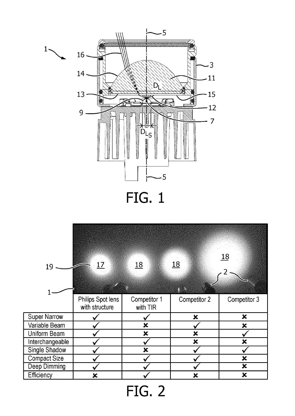
[0049]FIG. 1 shows a cross-section of a first embodiment of a lighting device 1 according to the invention. The lighting device comprises a housing 3 centrally arranged around an optical axis 5 and accommodates a light source 7 centrally mounted on the optical axis. The light source in the figure is a LED comprising a dome 9 with a diameter DLS of about 1 cm, the LED issuing a primary light beam 12. The housing further comprises a glass lens 11, i.e. LIBA 2000, centrally mounted on the optical axis and having a lens diameter DL of about 7 cm and being moveable with respect to light source along and / or over the optical axis. The lens has a light entry surface 13 and a light exit surface 14, the light entry surface is provided with a mixing structure 15 having a bluffing strength of about 4.5° FWHM, the bluffing having a Gaussian distribution. The lighting device issues a secondary light beam 16.

[0050]FIG. 2 gives an impression of beam spots of and properties of secondary beams as obt...


PUM


Abstract

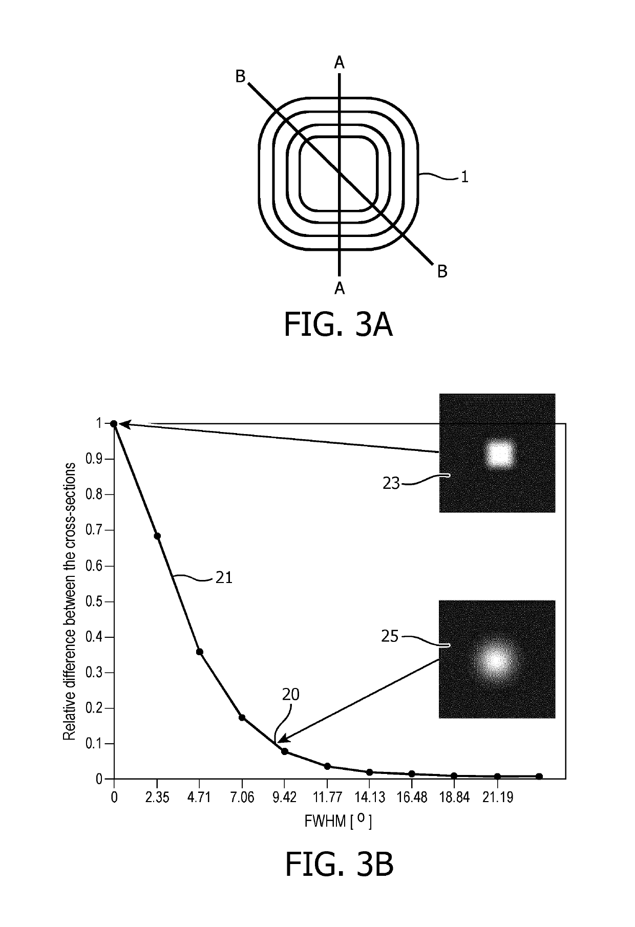
The invention relates to a lighting device for issuing a light beam in a main direction along an optical axis. The lighting device comprises a light source and a positive, refractive lens provided on the optical axis, the lens being movable with respect to the light source over the optical axis. The lighting device further comprises a mixing structure provided on the optical axis and having an added blurring strength FWHM, with FWHM being in a range of 3° to 15°.

Description

CROSS-REFERENCE TO PRIOR APPLICATIONS[0001]This application is the U.S. National Phase application under 35 U.S.C. § 371 of International Application No. PCT / EP2016 / 060551, filed on May 11, 2016 which claims the benefit of European Patent Application No. 15168365.3, filed on May 20, 2015. These applications are hereby incorporated by reference herein.FIELD OF THE INVENTION[0002]The invention relates to a lighting device comprising a light source for issuing light in a main direction along an optical axis and a lens provided on the optical axis. The invention further relates to a lens and a method to obtain a desired or required quality of a light beam.BACKGROUND OF THE INVENTION[0003]Nowadays spot lighting devices are applied largely in retail lighting and museum lighting. The light distribution is mainly defined by the light source and the optical solution, i.e. an optical part, such as a reflector, TIR-collimator or lens. Each optical solution has its own properties, advantages an...

Claims


Application Information

Patent Timeline
Patent Type & Authority Patents(United States)
IPC IPC(8): F21K9/60F21V13/00F21V14/06F21V5/04G02B5/02F21V5/00F21K9/62F21Y101/00F21Y115/10
CPCF21V5/04F21K9/62F21V5/002F21V13/00G02B5/02G02B5/0278F21V14/06F21Y2115/10F21K9/60F21Y2101/00
Inventor THIJSSEN, JOHANNES MARIAFORNASA, FABIOSEPKHANOV, RUSIAN AKHMEDOVICHVAN DE WOUW, INGE
Owner SIGNIFY HLDG BV
Learn More