Eureka AIR delivers breakthrough ideas for toughest innovation challenges, trusted by R&D personnel around the world.

Low swap laser pump diode module and laser amplifier incorporating the same

a laser pump and laser amplifier technology, applied in lasers, semiconductor laser structural details, semiconductor lasers, etc., can solve the problems of adding significant excess mass and volume to laser systems, and affecting the performance of laser systems. , to achieve the effect of limiting the scope of invention

Active Publication Date: 2019-03-26
NLIGHT INC
View PDF5 Cites 2 Cited by
  • Summary
  • Abstract
  • Description
  • Claims
  • Application Information

AI Technical Summary

Benefits of technology

[0007]Included in the disclosure herein is a laser assembly comprising a plurality H of distinct, spaced-apart heatsinks for mounting a respective plurality of distinct, spaced apart laser diodes. The heatsinks have respective diode mounting members, and the diode mounting members have respective attachment surfaces for receiving respective laser diodes. The laser assembly also comprises a carrier having a plurality M of fluid coolant flow channels for conducting a coolant from an inlet of the carrier, through the carrier, to an outlet of the carrier. Each of the channels is configured to conduct the coolant past a predetermined number N of the heatsinks in series, where M multiplied by N equals H, and where, for a given coolant and a given rate of heat generation by the laser diodes, a coolant mass flow rate F of the coolant through the carrier, a coolant pressure drop P of the coolant across the carrier, and a steady state temperature T of the laser diodes, depends on the combination of M and N. This allows for selecting M and N to vary the combinations of the variables F, P and T uniquely and significantly, and thereby allowing for optimizing said variables for a particular application.

Problems solved by technology

This adds significant excess mass and volume to a laser system.
However, for many DoD applications, size, weight and power (SWAP) consumption are still too large.
Moreover, for sake of simplicity, the attached figures may not show the various ways in which the disclosed systems, apparatuses, and methods can be used in conjunction with other systems, apparatuses, and methods.
Such configurations are susceptible to optic or fiber movement with the sidewalls of the package, which are mechanically removed from the laser / optics typically attached to the base of the package.
Additionally, during fabrication and brazing or firing of the electrical pins to the sidewall, the materials in the base, typically copper or an alloy of copper, anneal during the firing process, causing the base to become soft and easily deformed.
Holes used to screw down packages will often result in a slightly defoinied base surface, causing a non-flat base on the package.
Subsequent attachment of the package to other surfaces will result in a gap between the package and the mounting surface, reducing thermal transfer, increasing operating temperature of laser diodes within the package, and reducing reliability or varying laser wavelength outside of acceptable tolerance for particular applications.
In typical examples, an entire interior surface of the laser diode package and electrical pins is gold plated to provide solderability for various diode package components, but the gold plating can be applied to some surfaces unnecessarily, such as side surfaces, thereby wasting gold material and increasing costs.
As the package housings increase in size, the packages become prohibitively expensive and heavy, which increases cost, decreases suitability for various low-weight applications, and increases susceptibility to stress and handling damage.
Multiple pins or large pins are needed for larger currents, but the connectors typically needed are relatively expensive.
A large amount of machining with complex tolerances is required and a larger surface area must be plated.
LSLD assemblies generate significant amounts of heat during operation.
Bars have inherent “smile” issues which result in “rogue” beams that are not unidirectional, degrade beam quality, and introduce high numerical aperture cladding-light when coupled into fibers.
Deformation due to heating of carrier structure 204 may cause misalignment of optical components described above with respect to FIG. 6B, among other problems.

Method used


Image

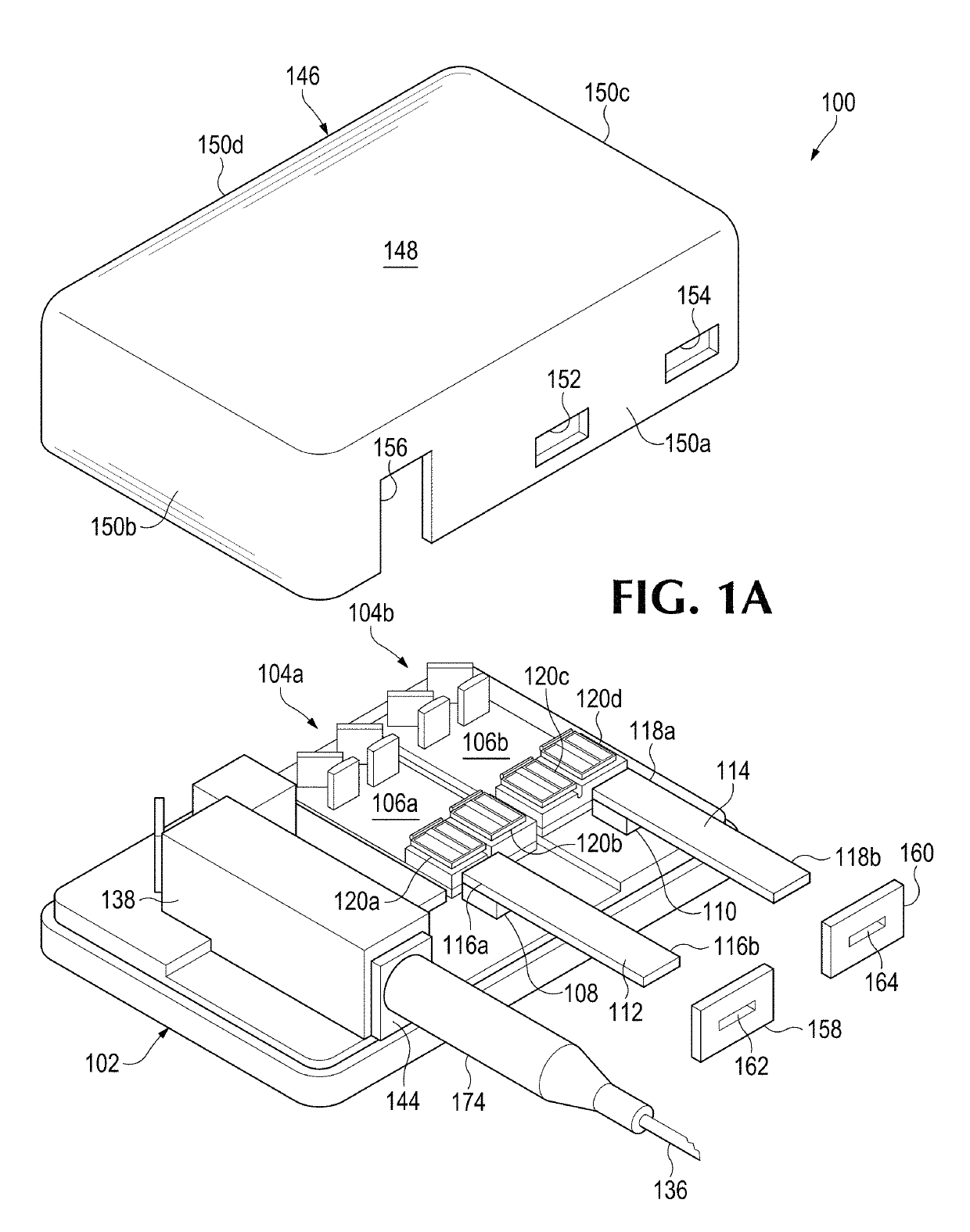
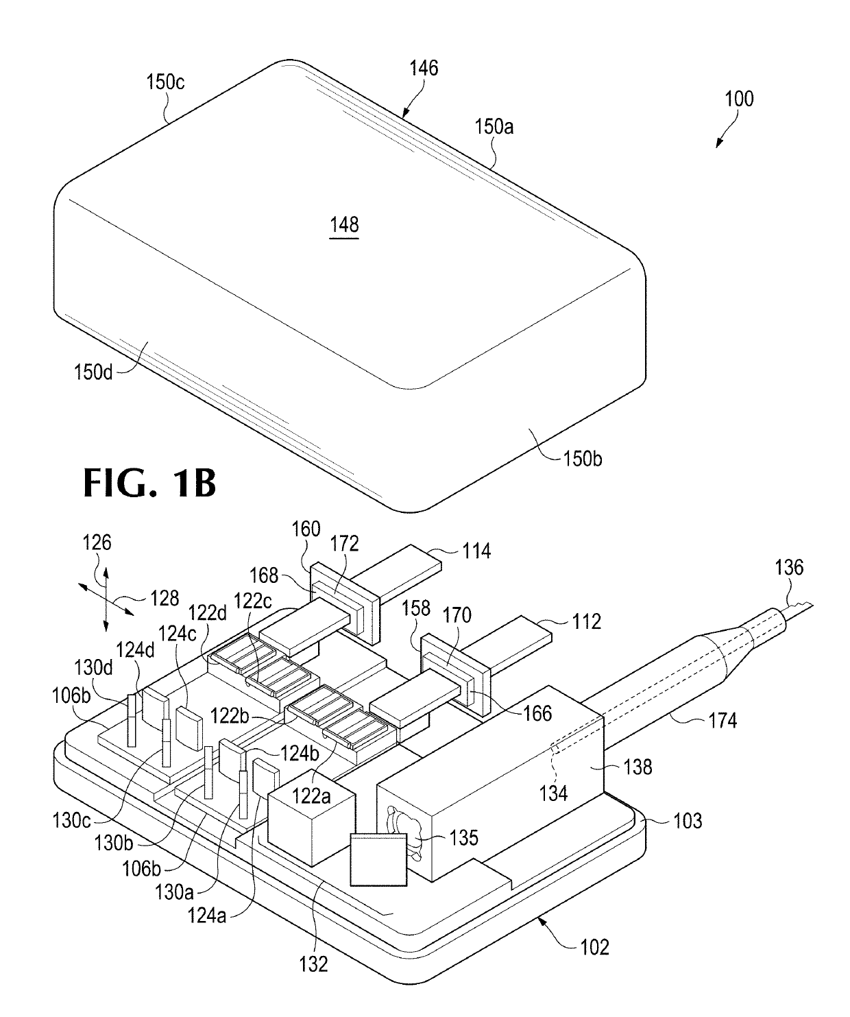
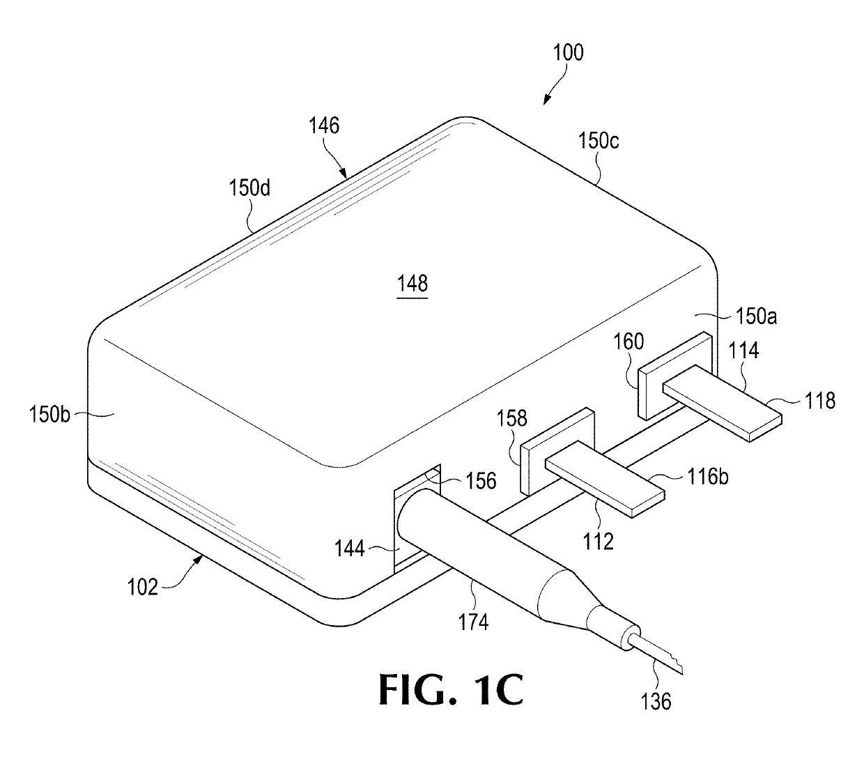
  • Low swap laser pump diode module and laser amplifier incorporating the same
  • Low swap laser pump diode module and laser amplifier incorporating the same
  • Low swap laser pump diode module and laser amplifier incorporating the same

Examples


Embodiment Construction

[0067]As used herein throughout this disclosure and in the claims, the singular forms “a,”“an,” and “the” include the plural forms unless the context clearly dictates otherwise. Additionally, the terms “includes” means “comprises.” Further, the term “coupled” does not exclude the presence of intermediate elements between the coupled items. Still further, the terms “modify” and “adjust” are used interchangeably to mean “alter.”

[0068]The systems, apparatuses, and methods described herein should not be construed as limiting in any way. Instead, the present disclosure is directed to all novel and non-obvious features and aspects of the various disclosed embodiments, alone and in various combinations and sub-combinations with one another. The disclosed systems, apparatuses, and methods are not limited to any specific aspect or feature or combinations thereof, nor do the disclosed systems, apparatuses, and methods require that any one or more specific advantages be present or problems be ...


PUM


Abstract

Disclosed herein are Low Size Weight and Power efficient Laser Diode pump modules and High Power Fiber Amplifiers incorporating such pump modules for amplifying laser light produced by a seed laser. The pump modules are configured for forced fluid cooling, and are provided with cooling channels that allow for varying combinations of a coolant mass flow rate F of the coolant, a pressure drop P of the coolant, and a steady state temperature T of the laser diodes in the pump modules, uniquely and significantly, and thereby allowing for optimizing such variables for a particular application.

Description

CROSS-REFERENCE TO RELATED APPLICATIONS[0001]This application claims priority from, and the benefit of, U.S. nonprovisional patent application Ser. No. 15 / 498,422, filed Apr. 26, 2017, which claims priority from, and the benefit of, U.S. provisional patent application Ser. No. 62 / 327,971, filed Apr. 26, 2016, and U.S. provisional patent application Ser. No. 62 / 458,569, filed Feb. 13, 2017. This application also claims priority from, and the benefit of, U.S. provisional patent application Ser. No. 62 / 492,869, filed May 1, 2017. All of the aforementioned applications are incorporated by reference herein in their entireties.TECHNICAL FIELD[0002]This invention relates primarily to thermal management of low size, weight and power efficient laser diode pump modules and optical fiber coupled laser amplifiers incorporating the same.BACKGROUND[0003]Most fiber-coupled laser (Light Amplification by Stimulated Emission of Radiation) diode pumps have been developed for large volume industrial ap...

Claims


Application Information

Patent Timeline
Patent Type & Authority Patents(United States)
IPC IPC(8): H01S5/02H01S5/022H01S5/024H01S3/094H01S3/04H01S3/0941H01S5/02315H01S5/0233
CPCH01S5/02423H01S3/0401H01S3/0407H01S5/02288H01S3/094003H01S5/02284H01S3/09415H01S3/06704H01S3/06758H01S5/005H01S5/0071H01S5/02H01S5/02216H01S5/02476H01S5/4012H01S5/4056H01S5/02326H01S5/02345H01S5/0233H01S5/0235H01S5/02251H01S5/02315H01S5/02253
Inventor KANSKAR, MANOJBOELEN, JOHANNES
Owner NLIGHT INC
Why Eureka
Eureka Blog
Learn More