
Semiconductor structure and fabricating method thereof

a technology of semiconductor devices and semiconductor devices, applied in the direction of semiconductor devices, electrical equipment, transistors, etc., can solve the problems of constant decrease of the dimensions of semiconductor devices, leakage current, and affecting the electrical properties of semiconductor devices

Active Publication Date: 2019-03-05
SEMICON MFG INT (SHANGHAI) CORP +1
View PDF18 Cites 0 Cited by
  • Summary
  • Abstract
  • Description
  • Claims
  • Application Information

AI Technical Summary

Benefits of technology

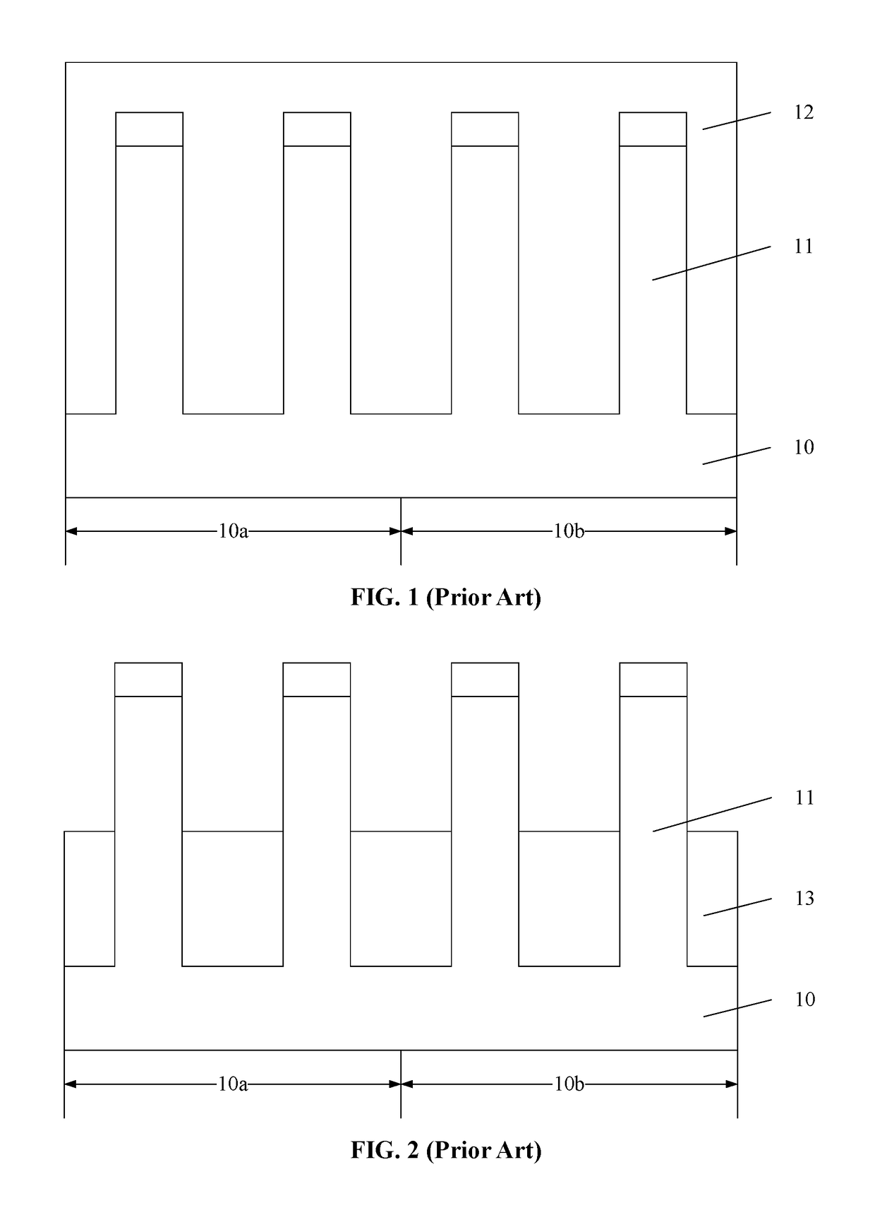
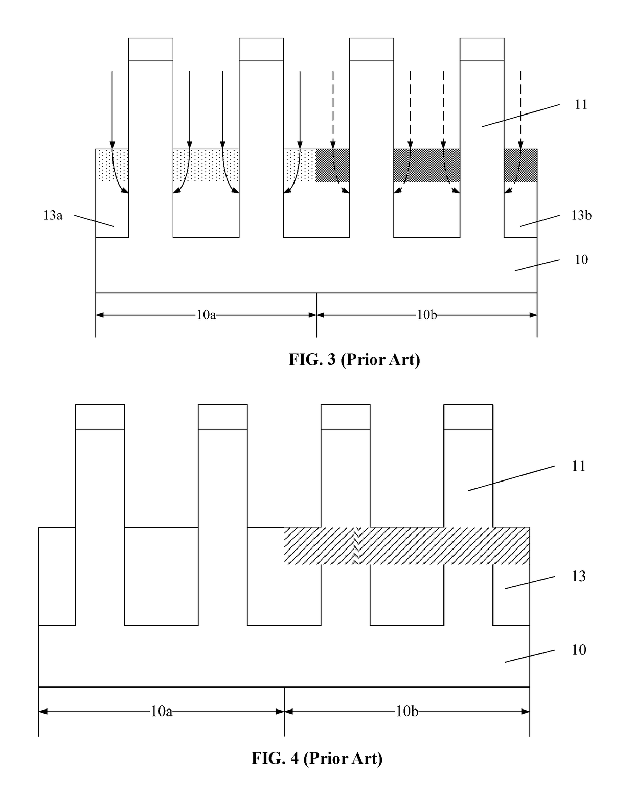
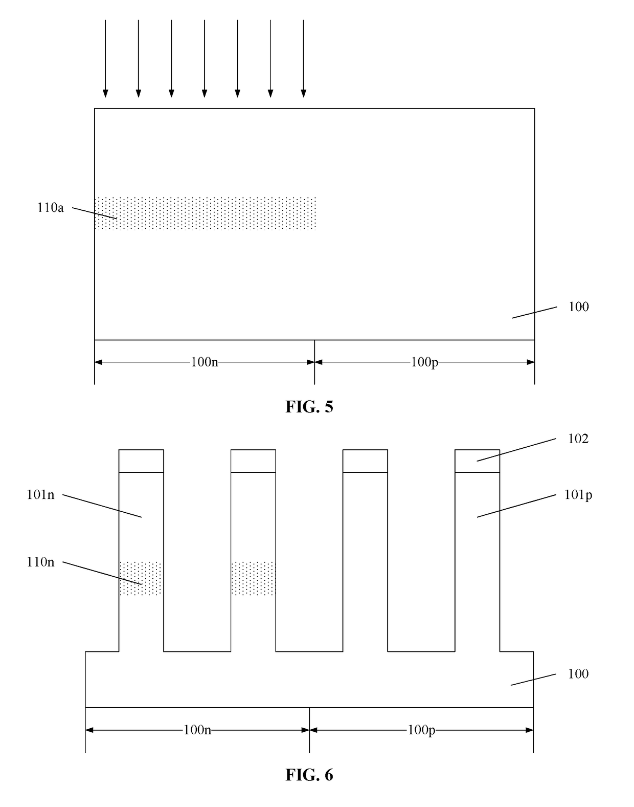
[0043]In the disclosed fabricating process, the first punch-through preventing ions can be implanted directly into the NMOS region of the substrate to form the first implantation layer, then multiple fin portions can be formed by etching the substrate. The substrate surfaces between the first fin portions in the NMOS region are lower than the first implantation layer. The remaining first implantation layer in the first fin portions that is not etched forms the first punch-through preventing layer. As such, the first punch-through preventing ions are mainly distributed in the first fin portions. That is, the diffusion of the first punch-through preventing ions can be restrained, a dose loss of the first punch-through preventing ions due to the diffusion can be eliminated, and a possibility that the first punch-through preventing ions diffuse into the PMOS region is reduced. Therefore, the performance of the fabricated semiconductor structure can be improved, and the manufacturing yield of the semiconductor structure can be ensured.
[0043]In the disclosed fabricating process, the first punch-through preventing ions can be implanted directly into the NMOS region of the substrate to form the first implantation layer, then multiple fin portions can be formed by etching the substrate. The substrate surfaces between the first fin portions in the NMOS region are lower than the first implantation layer. The remaining first implantation layer in the first fin portions that is not etched forms the first punch-through preventing layer. As such, the first punch-through preventing ions are mainly distributed in the first fin portions. That is, the diffusion of the first punch-through preventing ions can be restrained, a dose loss of the first punch-through preventing ions due to the diffusion can be eliminated, and a possibility that the first punch-through preventing ions diffuse into the PMOS region is reduced. Therefore, the performance of the fabricated semiconductor structure can be improved, and the manufacturing yield of the semiconductor structure can be ensured.
[0017]Another aspect of the disclosed subject matter provides another method for forming a semiconductor structure, comprising: providing a substrate including an NMOS region and a PMOS region that are adjacent to each other; implanting first punch-through preventing ions into the NMOS region of the substrate to form a first implantation layer; etching the substrate to form a plurality of fin portions, including first fin portions in the NMOS region, and second fin portions in the PMOS region, wherein: surfaces of the substrate between the first fin portions in the NMOS region are lower than the first implantation layer, and the remaining first implantation layer in the first fin portions that is not etched forms a first punch-through preventing layer; forming insulating structures between adjacent first fin portions and second fin portions, wherein surfaces of the insulating structure are higher than top surfaces of the first punch-through preventing layer; after forming the insulating structures, implanting second punch-through preventing ions into the PMOS region of the substrate, and making the second punch-through preventing ions diffuse into the second fin portions to form a second punch-through preventing layer; and performing an annealing process to activate the first punch-through preventing layer and the second punch-through preventing layer.

Problems solved by technology

Thus the traditional planar transistors may have a weakened control ability to the channel current, resulting in short-channel effects which can generate leakage current.
Ultimately, electrical properties of the semiconductor devices can be affected.
However, as the dimensions of semiconductor devices continually decrease, the Fin FET manufacturing process has been challenged.
It is difficult to ensure a stable performance of the Fin FET.

Method used


Image

  • Semiconductor structure and fabricating method thereof
  • Semiconductor structure and fabricating method thereof
  • Semiconductor structure and fabricating method thereof

Examples


Embodiment Construction

[0025]Various objects, features, and advantages of the disclosed subject matter can be more fully appreciated with reference to the following detailed description of the disclosed subject matter when considered in connection with the following drawings, in which like reference numerals identify like elements. It should be noted that the following drawings are merely examples for illustrative purposes according to various disclosed embodiments and are not intended to limit the scope of one disclosure.

[0026]It is apparent that the described embodiments are some but not all of the embodiments of the present invention. Based on the disclosed embodiments, persons of ordinary skill in the art may derive other embodiments consistent with the present disclosure, all of which are within the scope of the present invention.

[0027]As the dimensions of semiconductor devices continually decrease, the Fin FET manufacturing process has been challenged. It is difficult to ensure a stable performance ...


PUM


Abstract

In various embodiments of the disclosed subject matter, a semiconductor structure, and a fabricating method thereof are provided. The method for forming a semiconductor structure comprises: providing a substrate; implanting first punch-through preventing ions into an NMOS region of the substrate to form a first implantation layer; implanting second punch-through preventing ions into a PMOS region of the substrate to form a second implantation layer; etching the substrate to form first fin portions in the NMOS region, and second fin portions in the PMOS region, the remaining first implantation layer forms a first punch-through preventing layer, the remaining second implantation layer forms a second punch-through preventing layer; forming insulating structures between adjacent first fin portions and second fin portions; and performing an annealing process to activate the first punch-through preventing layer and the second punch-through preventing layer.

Description

CROSS-REFERENCES TO RELATED APPLICATIONS[0001]This application claims the priority of Chinese patent application No. 201510690768.0, filed on Oct. 22, 2015, the entire content of which is incorporated herein by reference.TECHNICAL FIELD[0002]The present disclosure generally relates to the field of semiconductor technologies and, more particularly, relates to a semiconductor structure, and a fabricating method thereof.BACKGROUND[0003]With the rapid development of semiconductor manufacturing technology, semiconductor devices have been developed for higher component density and higher degree of integration. Transistors, as the basic semiconductor devices, are currently being widely used. With the improvement of the component density and integration degree of the semiconductor devices, the gate sizes of planar transistors are getting shorter. Thus the traditional planar transistors may have a weakened control ability to the channel current, resulting in short-channel effects which can g...

Claims


Application Information

Patent Timeline
Patent Type & Authority Patents(United States)
IPC IPC(8): H01L21/306H01L29/66H01L21/324H01L21/8238H01L27/092H01L21/265
CPCH01L21/823807H01L21/265H01L21/30604H01L29/66803H01L21/823821H01L21/823857H01L27/0924H01L21/324H01L29/66795
Inventor ZHOU, FEI
Owner SEMICON MFG INT (SHANGHAI) CORP
Learn More