Medical treatment system and methods using a plurality of fluid lines
What is Al technical title?
Al technical title is built by PatSnap Al team. It summarizes the technical point description of the patent document.
a treatment system and fluid line technology, applied in the field of medical treatment system and method using a plurality of fluid lines, can solve the problems of dampening the acceptance of apd as an alternative by the general population, unable to meet the needs of patients, so as to reduce touch or leakage current and control current delivery
Active Publication Date: 2019-02-12
DEKA PROD LLP
View PDF202 Cites 32 Cited by
Summary
Abstract
Description
Claims
Application Information
AI Technical Summary
This helps you quickly interpret patents by identifying the three key elements:
Problems solved by technology
Method used
Benefits of technology
[0045]The method can further comprise: repeating the steps of making, charging, firstly recording the pressure, connecting, allowing, recording the volume, secondly recording the pressure, and determining until substantially all the liquid in pump chamber has been expelled; storing the calibration coefficient and the provisional volume measurements as a related pairs; and fitting a calibration equation to the stored values of calibration coefficient as a function of the related provisional volume measurements. The accuracy of the determined volumes of the pump control chamber can be improved by averaging 1) a given determined volume, 2) the preceding determined volume plus the preceding displaced water volume, and 3) the following determined volume minus the following displaced water volume. The accuracy of the first determined volume of the pump control chamber can also be improved by averaging 1) the first determined volume, and 2) the following determined volume minus the following displaced water volume. The accuracy of the last determined volume of the pump control chamber can also be improved by averaging 1) the last determined volume, and 2) the preceding determined volume plus the preceding displaced water volume.
[0062]In another aspect, a system is disclosed for performing automated peritoneal dialysis comprising; a cycler comprising a fluid pump and controller, the controller configured to measure and control an amount of fluid pumped to a peritoneal cavity and to track a remaining volume of the fluid in a solution bag. The controller is configured to: control a dialysis therapy by administering a pre-determined number of therapy cycles, each therapy cycle comprising a fill phase, dwell phase and drain phase; and maintain a pre-determined minimum volume of intra-peritoneal fluid during the dwell phase. It is also configured to cancel a final therapy cycle if a calculated final volume of fluid remaining in the solution bag for the final therapy cycle is less than a volume required to maintain the minimum intra-peritoneal fluid volume for the final therapy cycle dwell phase; divide the remaining final volume of fluid in the solution bag among a remaining number of therapy cycle fill volumes; and divide a duration of the final therapy cycle dwell phase among a remaining number of therapy cycle dwell phases. The controller is also configured to further adjust the fill volumes of the remaining number of therapy cycles, or the duration of the dwell phases of the remaining number of therapy cycles to prevent an accumulation of intra-peritoneal fluid during the remaining therapy cycles from exceeding a pre-determined maximum intra-peritoneal volume of fluid.
[0071]In another aspect, an electronic circuit is disclosed for reducing touch or leakage current from a heating element of an automated peritoneal dialysis apparatus. The circuit comprises: a first relay connecting a first pole of an AC mains source to a first end of the heating element; a second relay connecting a second pole of the AC mains source to a second end of the heating element; and a controller configured to control current delivery to the heating element by transmitting an on signal to both the first and second relays or an off signal to both the first and second relays, the on signal causing AC mains current to flow through the heating element, and the off signal preventing AC mains current from flowing through the heating element. The heating element is isolated from AC mains voltage when the controller transmits an off signal.
Problems solved by technology
IPD can also be used when a patient requires PD, but cannot undertake the responsibilities of CAPD or otherwise do it at home.
Still, the complexity and size of past machines and associated disposables for various APD modalities have dampened widespread patient acceptance of APD as an alternative to manual peritoneal dialysis methods.
Method used
Image
Click on the blue label to locate the original text in one second.
Reading with bidirectional positioning of images and text.
Examples
Embodiment Construction
[0302]Although aspects of the invention are described in relation to a peritoneal dialysis system, certain aspects of the invention can be used in other medical applications, including infusion systems such as intravenous infusion systems or extracorporeal blood flow systems, and irrigation and / or fluid exchange systems for the stomach, intestinal tract, urinary bladder, pleural space or other body or organ cavity. Thus, aspects of the invention are not limited to use in peritoneal dialysis in particular, or dialysis in general.
[0303]APD System
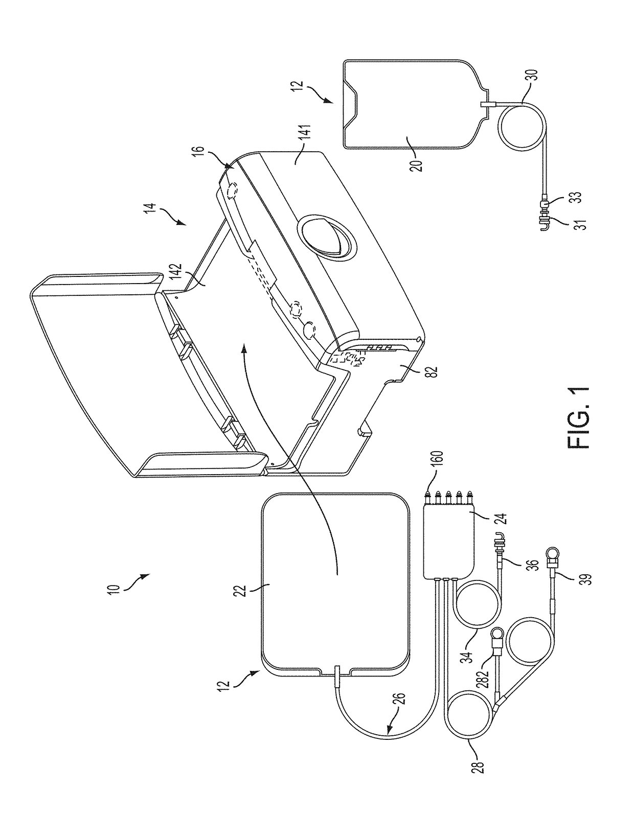
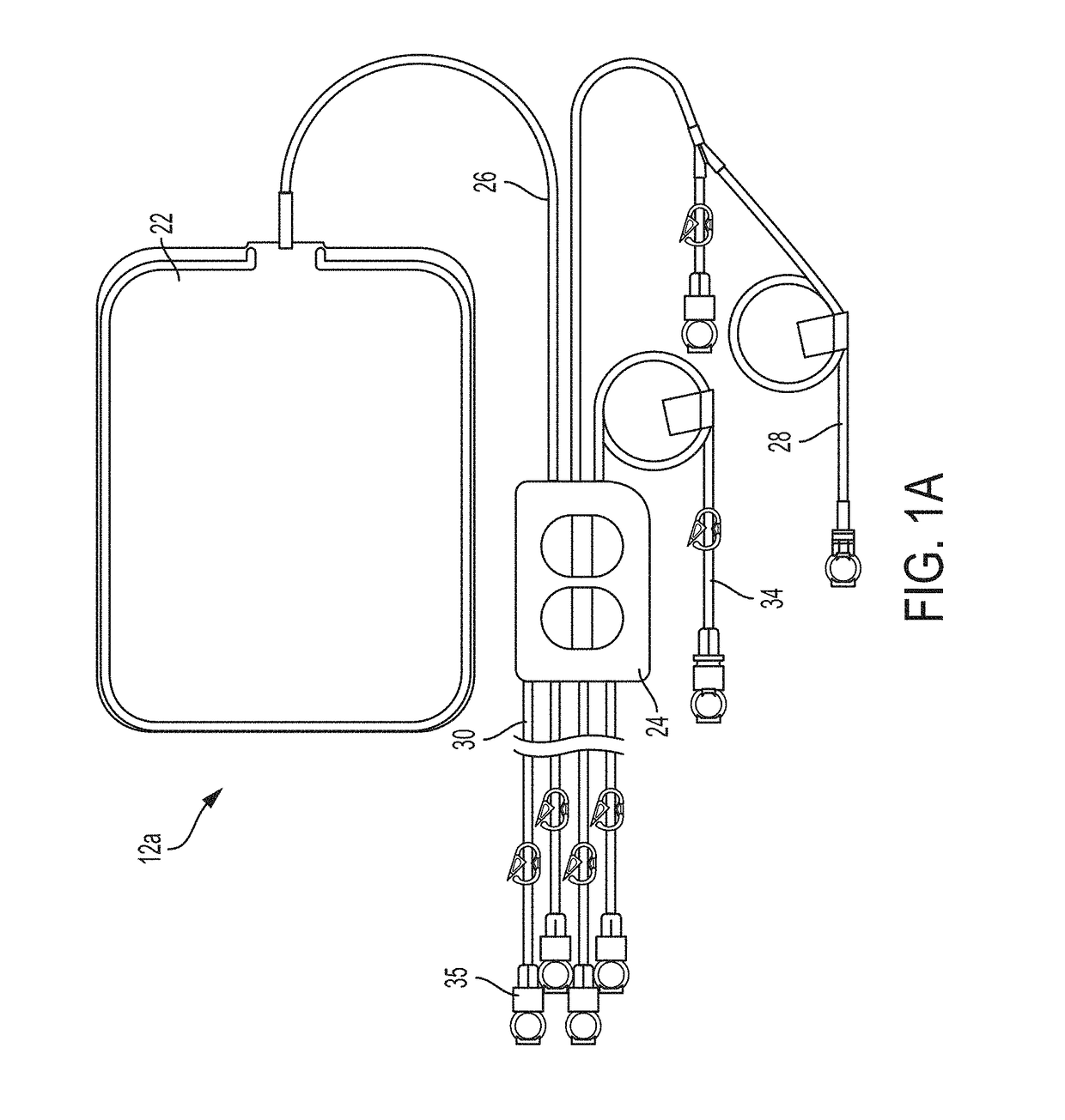
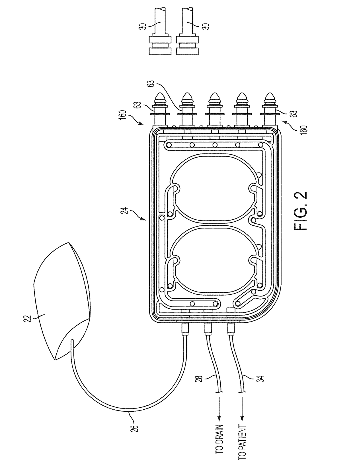
[0304]FIG. 1 shows an automated peritoneal dialysis (APD) system 10 that may incorporate one or more aspects of the invention. As shown in FIG. 1, for example, the system 10 in this illustrative embodiment includes a dialysate delivery set 12 (which, in certain embodiments, can be a disposable set), a cycler 14 that interacts with the delivery set 12 to pump liquid provided by a solution container 20 (e.g., a bag), and a control system 16 (e.g...
PUM
Abstract
Improvements in fluid volume measurement systems are disclosed for a pneumatically actuated diaphragm pump in general, and a peritoneal dialysis cycler using a pump cassette in particular. Pump fluid volume measurements are based on pressure measurements in a pump control chamber and a reference chamber in a two-chamber model, with different sections of the apparatus being modeled using a combination of adiabatic, isothermal and polytropic processes. Real time or instantaneous fluid flow measurements in a pump chamber of a diaphragm pump are also disclosed, in this case using a one-chamber ideal gas model and using a high speed processor to obtain and process pump control chamber pressures during fluid flow into or out of the pump chamber. Improved heater control circuitry is also disclosed, to provide added or redundant safety measures, or to reduce current leakage from a heater element during pulse width modulation control of the heater. Improvements are also disclosed in the application of negative pressure during a drain phase in peritoneal dialysis therapy, and to control the amount of intraperitoneal fluid accumulation during a therapy. Improvements in efficiency are also disclosed in the movement of fluid into and out of a two-pump cassette and heater bag of a peritoneal dialysis cycler, and in the synchronization of the operation of two or more pumps in a peritoneal dialysis cycler or other fluid handling devices using a multi-pump arrangement.
Description
CROSS REFERENCE TO RELATED APPLICATIONS[0001]This application is a continuation in part of U.S. application Ser. No. 13 / 667,696, filed Nov. 2, 2012, now U.S. Pat. No. 9,078,971, issued Jul. 14, 2015, which is a continuation in part of U.S. application Ser. No. 13 / 178,191, filed Jul. 7, 2011, now U.S. Pat. No. 8,708,950, issued Apr. 29, 2014, which claims the benefit of U.S. Provisional Application No. 61 / 362,259, filed Jul. 7, 2010.[0002]U.S. application Ser. No. 13 / 667,696 is also a continuation in part of U.S. application Ser. No. 12 / 864,357, filed Jul. 23, 2010 and entered the national stage on Dec. 13, 2010, now U.S. Pat. No. 9,248,225, issued Feb. 2, 2016, which is a national stage of PCT application PCT / US2009 / 000440, filed Jan. 23, 2009, which claims the benefit of U.S. Provisional Application No. 61 / 011,967, filed Jan. 23, 2008 and U.S. Provisional Application No. 61 / 058,469, filed Jun. 3, 2008.[0003]U.S. application Ser. No. 13 / 667,696 is also a continuation in part of U.S....
Claims
Application Information
Patent Timeline
Application Date:The date an application was filed.
Publication Date:The date a patent or application was officially published.
First Publication Date:The earliest publication date of a patent with the same application number.
Issue Date:Publication date of the patent grant document.
PCT Entry Date:The Entry date of PCT National Phase.
Estimated Expiry Date:The statutory expiry date of a patent right according to the Patent Law, and it is the longest term of protection that the patent right can achieve without the termination of the patent right due to other reasons(Term extension factor has been taken into account ).
Invalid Date:Actual expiry date is based on effective date or publication date of legal transaction data of invalid patent.
Inventor NORRIS, MICHAEL G.SCARPACI, JACOB W.BRYANT, JR., ROBERT J.SPENCER, GEOFFREY P.HIBBARD, DAVID J.DALE, JAMES D.KERWIN, JOHN M.COLL, ANDREW S.BEAVERS, DAVID A.MCGILL, DAVID W.HELMORE, SIMON C.DOHERTY, DAVID B.BOLTON, EDGAR J.YOO, JINSUNGIROUARD, PAUL G.KAROL, DANIEL S.SINGER, DANIEL B.RUSHLOW, JOSEPH P.