Process for increasing process furnaces energy efficiency

a technology of process furnace and energy efficiency, which is applied in the direction of hydrocarbon preparation, combined combustion mitigation, and thermal non-catalytic cracking. it can solve the problems of limited heat supply to the process (and thus energy saving potential), limited gas turbine, and limited gas turbine. , to achieve the effect of increasing steam cracker energy efficiency, reducing the negative effect of gas turbine trip, and reducing the negative effect of gas turbin

Active Publication Date: 2019-01-29
SAUDI BASIC IND CORP SA +1
View PDF24 Cites 1 Cited by
  • Summary
  • Abstract
  • Description
  • Claims
  • Application Information

AI Technical Summary

Benefits of technology

[0015]Another object of the present invention is to provide a process for increasing steam cracker energy efficiency through gas turbine

Problems solved by technology

The heat supply to the process (and thus energy savings potential) is limited by the combustion air requirements of the steam cracking furnaces, the size of the gas turbine is limited by the combustion air requirements in the furnaces, limiting possible scale advantages of larger gas turbines.
This means that the operation scale of this technology is dictated by the intimate technical relationship between the steam cracking furnaces and the combined heat and power (CHP) resulting in some possible neg

Method used


Image

  • Process for increasing process furnaces energy efficiency

Examples


Embodiment Construction

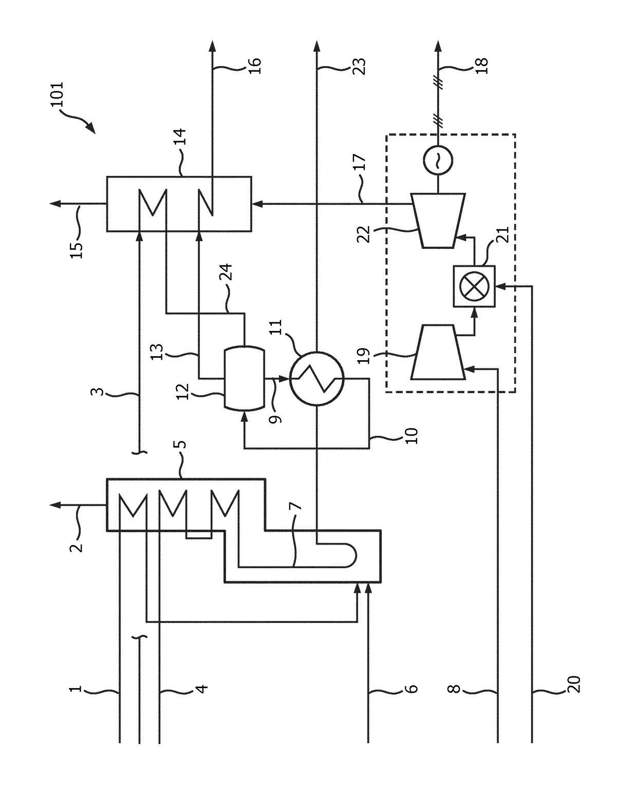
[0045]Combustion air 1 is sent to a section of furnace 5. In furnace 5 stream 4, comprising process feed, is heated in a first preheating section and further heated and cracked in the radiant coils 7 of the radiant section of furnace 5. Furnace 5 is heated through stream 6, comprising fuel. Combustion air 1 is preheated through hot flue gasses 2 from cracking furnace 5. It is also possible (not shown) to preheat combustion air 1 in a section of heat recovery unit 14. The cracked hydrocarbon feed coming from cracking furnace 5 is rapidly cooled by a transfer line exchanger (TLE) 11. Cooling is provided by water 9 from steam drum 12. In steam drum 12 water and steam are separated and the steam 13 produced in steam drum 12 is sent to a heat recovery unit 14. Saturated high pressure steam 13 is converted in super heated high pressure steam 16 after leaving heat recovery unit 14. In transfer line exchanger 11 water 9 coming from steam drum 12 is converted into a mixture 10 of water and s...


PUM


Abstract

A process for increasing furnace energy efficiency through gas turbine integration by using turbine exhaust gas, wherein a hydrocarbon feed is heated in a furnace.

Description

CROSS-REFERENCE TO RELATED APPLICATIONS[0001]This application is a national phase under 35 U.S.C. § 371 of International Application No. PCT / EP2014 / 079172, filed Dec. 23, 2014, which claims the benefit of priority to European Patent Application No. 14156624.0, filed Feb. 25, 2014, the entire contents of each of which are hereby incorporated by reference in their entirety.TECHNICAL FIELD AND BACKGROUND OF THE INVENTION[0002]The present invention relates to a process for increasing process furnaces energy efficiency through gas turbine integration by using turbine exhaust gas, wherein a hydrocarbon feed is heated in a furnace. More in detail, the present invention relates to the increased energy efficiency of steam cracking by gas turbine integration.[0003]U.S. Pat. No. 4,172,857 relates to a non-catalytic cracking process employing a pressurized riser-type thermal cracker heated by hot agglomerated ash particles circulated from a separate coal burning power producing combustion unit....

Claims


Application Information

Patent Timeline
IPC IPC(8): C10G9/36C10G9/00C10G9/14F02C6/18C07C5/327
CPCC10G9/36C07C5/327C10G9/14F02C6/18C10G9/002Y02E20/14
Inventor VAN WILLIGENBURG, JORIS
Owner SAUDI BASIC IND CORP SA
Why Eureka
Try Eureka