
Mobile terminal

a mobile terminal and terminal technology, applied in the field of mobile terminals, can solve the problems of separation, deterioration of the stiffness of the rear case coupled to the non-conductive material, etc., and achieve the effect of reducing stiffness and minimizing the performance degradation of the antenna

Active Publication Date: 2019-01-08
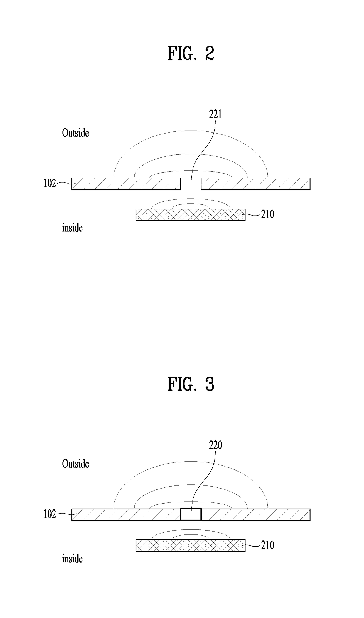
LG ELECTRONICS INC
View PDF10 Cites 1 Cited by
  • Summary
  • Abstract
  • Description
  • Claims
  • Application Information

AI Technical Summary

Benefits of technology

The solution maintains radiation performance, improves coupling reliability, increases stiffness, and prevents electromagnetic interference from affecting other components, while maintaining an aesthetically consistent exterior design.

Problems solved by technology

Especially, such NFC antenna is overly weighed in a back side of a mobile terminal so as to bring a radiation effect toward the backside of the mobile terminal.
However, when the thickness of the non-conductive material is equal to that of the rear case, the coupling area, in other words, the contact area between the rear case and the non-conductive material is not so sufficient to cause a problem of separation and deteriorate the stiffness of the rear case coupled to the non-conductive material.

Method used


Image

  • Mobile terminal
  • Mobile terminal
  • Mobile terminal

Examples


Embodiment Construction

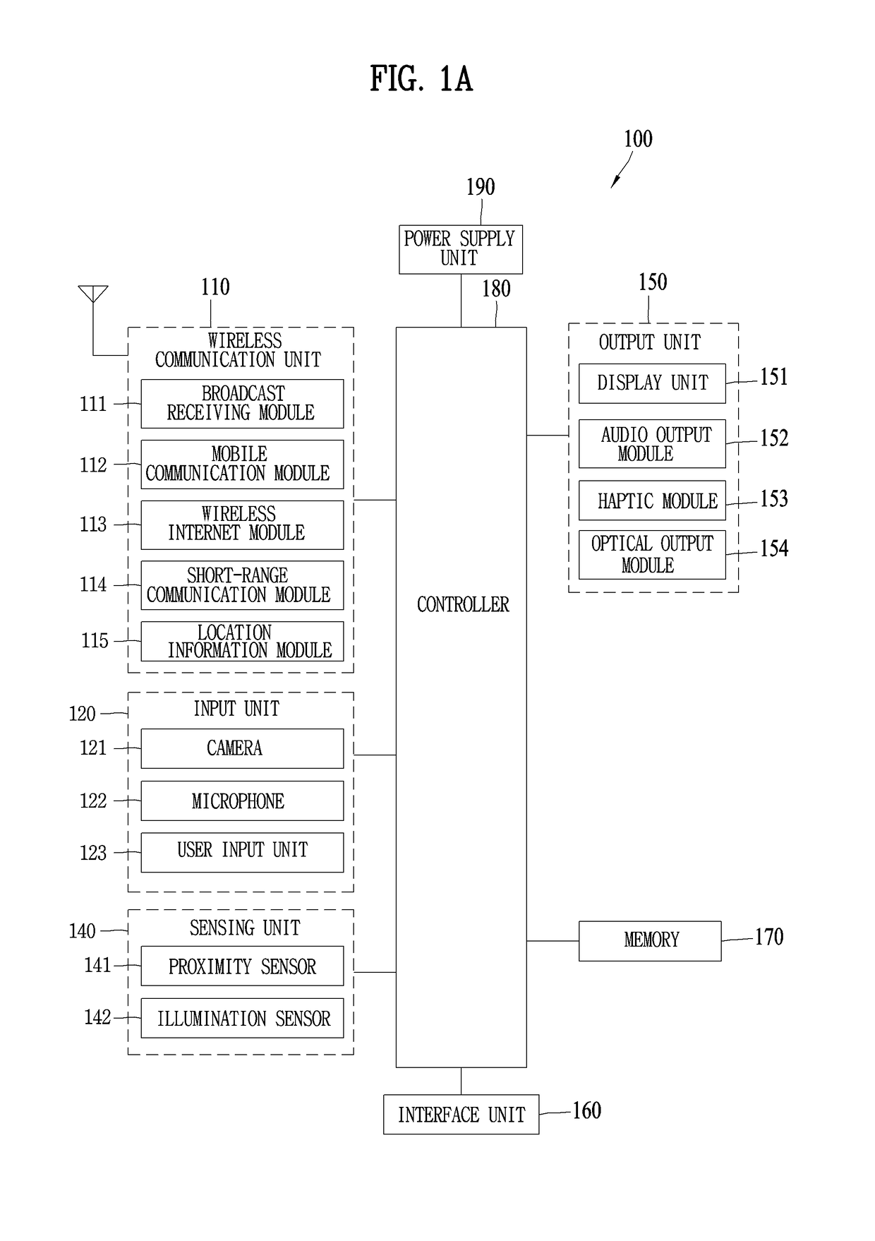
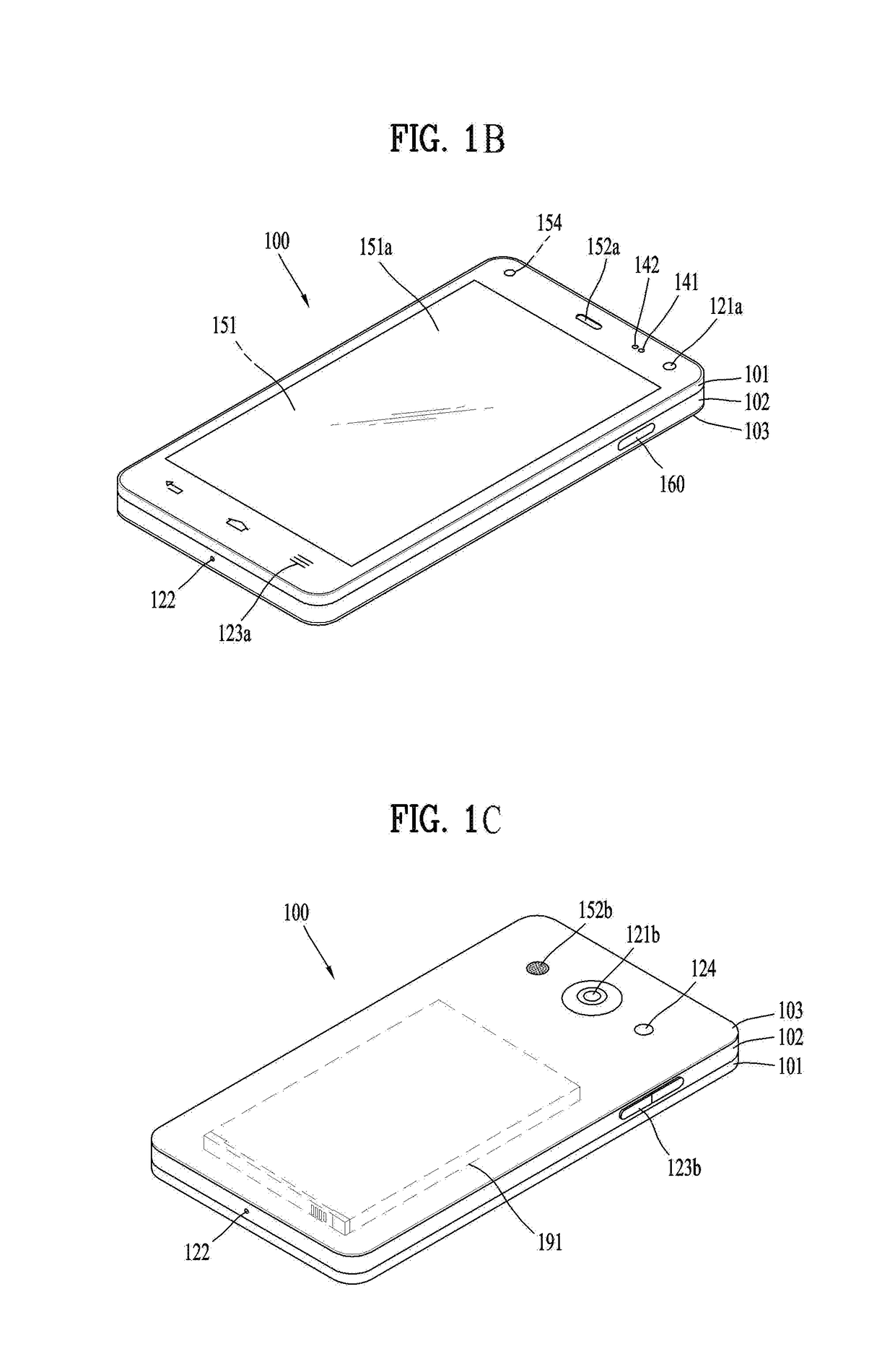
[0043]Description will now be given in detail according to exemplary embodiments disclosed herein, with reference to the accompanying drawings. For the sake of brief description with reference to the drawings, the same or equivalent components may be provided with the same reference numbers, and description thereof will not be repeated. In general, a suffix such as “module” and “unit” may be used to refer to elements or components. Use of such a suffix herein is merely intended to facilitate description of the specification, and the suffix itself is not intended to give any special meaning or function. In the present disclosure, that which is well-known to one of ordinary skill in the relevant art has generally been omitted for the sake of brevity. The accompanying drawings are used to help easily understand various technical features and it should be understood that the embodiments presented herein are not limited by the accompanying drawings. As such, the present disclosure should...


PUM


Abstract

There is disclosed a mobile terminal comprising a rear case made of metal and forming an exterior of a rear surface of the mobile terminal, the rear case comprising a first slit; a reinforcing member made of a non-conductive material, coupled to a first region of the rear having the first slit, wherein the reinforcing member protrude inward of the rear case and form an uneven portion; a first conductive pattern coupled to an inner surface of the rear case and forming a cut-off region in the first region, the first conductive pattern formed in a ring shape; and a second conductive pattern provided in a corresponding shape to uneven portion of the reinforcing member and electrically connecting the cut-off region of the first conductive pattern.

Description

CROSS-REFERENCE TO RELATED APPLICATIONS[0001]Pursuant to 35 U.S.C. § 119(a), this application claims the benefit of earlier filing date and right of priority to Korean Application No. 10-2016-0088465, filed on Jul. 13, 2016, the contents of which are hereby incorporated by reference herein in their entirety.BACKGROUND OF THE DISCLOSUREField of the Disclosure[0002]Embodiments of the present disclosure relate to a mobile terminal which has a metal exterior appearance to provide an antenna.Background of the Disclosure[0003]NFC antenna is capable of performing short range wireless communication. Especially, such NFC antenna is overly weighed in a back side of a mobile terminal so as to bring a radiation effect toward the backside of the mobile terminal.[0004]In case a rear case is made of metal, the wireless signal generated by the NFC antenna is unable to penetrate the rear case and travel outside because of the conductivity possessed by the metal.[0005]Accordingly, the metal rear case...

Claims


Application Information

Patent Timeline
Patent Type & Authority Patents(United States)
IPC IPC(8): H04B5/00H04B1/3888H05K1/02H05K5/00H05K5/02H05K9/00G06K19/077H04M1/18
CPCH04B1/3888G06K19/07777H04B5/0031H04B5/0081H05K9/0081H05K1/028H05K5/0086H05K5/0247H04M1/185H04M1/026H04M2250/04G06K7/10297H04B5/26H01Q1/2216H01Q7/00H04M1/0202H04B5/72
Inventor KIM, EUNAKIM, MINSOOKIM, YOUNGILMOON, BYEONGGI
Owner LG ELECTRONICS INC
Learn More