Cylinder head integrated with exhaust manifold and EGR cooler

a technology of cylinder head and exhaust manifold, which is applied in the direction of cylinders, mechanical equipment, machines/engines, etc., can solve the problems of affecting the performance and durability of the engine, the exhaust manifold has been a major issue, and the loss of performance, so as to reduce manufacturing costs and simplify the layout

Inactive Publication Date: 2018-12-04
HYUNDAI MOTOR CO LTD +1
View PDF28 Cites 0 Cited by
  • Summary
  • Abstract
  • Description
  • Claims
  • Application Information

AI Technical Summary

Benefits of technology

[0011]Various aspects of the present invention are directed to providing a cylinder head integrated with an exhaust manifold and an EGR (exhaust gas recirculation) cooler configured to be integrated by inserting both the exhaust manifold and the EGR cooler into the cylinder head of an engine, thereby realizing a simple layout and reducing manufacturing cost thereof.
[0021]According to the cylinder head integrated with the exhaust manifold and the EGR cooler configured as described above, the cylinder head is integrated with the exhaust manifold and the EGR cooler cylinder head by inserting the exhaust manifold and the EGR cooler into the cylinder head. Unlike a conventional EGR cooler, which is problematic in that a cooling fin of the EGR cooler is provided by being brazed outside stainless steel (SUS), and thus being expensive to manufacture, the cylinder head integrated with the exhaust manifold and the EGR cooler of the present invention is advantageous in that the housing of the EGR cooler can be made of the same material as the cylinder head, whereby it is possible to realize a simple layout and to reduce manufacturing cost thereof.
[0022]Further, the cylinder head integrated with the exhaust manifold and the EGR cooler of the present invention is advantageous in that a pipe, which is used to make the mounting surface of the cylinder head where the exhaust manifold is mounted and the connection area of the EGR cooler, can be removed or shortened in length by using the same material as the cylinder head. Thus, assembly time thereof can be reduced, whereby it is possible to reduce manufacturing cost.
[0023]When an EGR valve is operated at a beginning of a cold start of the engine during drive of a vehicle, a coolant cools EGR gas, whereby the temperature of the coolant is relatively raised. Thus, temperature losses of exhaust gas are relatively reduced, whereby the temperature of the exhaust gas that flows in front of a catalyst is relatively high, and thus it is possible to raise a catalyst activation temperature to a relatively high point. Further, a solenoid valve may be provided in a part that is operated by the EGR cooler in the cylinder head at the beginning of the cold start so that the coolant can be controlled not to flow by closing the solenoid valve at the beginning of the cold start. Thereby, it is possible to minimize the temperature losses of the exhaust gas caused by a circulation of the coolant. Therefore, it is possible to minimize a temperature decrease of the exhaust gas that flows in front of the catalyst, thereby reducing time for raising the catalyst activation temperature and realizing improved emissions. Alternatively, a variable flow control valve instead of the solenoid valve may be provided for preventing the coolant from flowing at the beginning of the cold start.
[0024]Further, a pipe for an EGR path may be removed or the length thereof may be shortened, thereby minimizing a difference in pressure via shortening the length of a connection passage. Thus, the EGR can be applied to a low speed / low load range, whereby efficiency of the engine can be improved by improving suction efficiency. Therefore, gas mileage can be improved.

Problems solved by technology

Generally, an exhaust manifold is developed as an additional component separately from a cylinder head and is mounted to the cylinder head, thereby frequently causing thermal damage to a vehicle as well as affecting performance and durability of an engine.
Thus, the exhaust manifold has been a major issue in a vehicle package.
The dramatic modification in the shape of the exhaust manifold results in it being disposed at an increased distance from the catalyst, results in losses in performance, reduced thermal durability, etc.
In the case that curvature of the shape of the exhaust manifold is dramatically changed, cracking may appear in a stress concentration area due to thermal fatigue.

Method used


Image

  • Cylinder head integrated with exhaust manifold and EGR cooler
  • Cylinder head integrated with exhaust manifold and EGR cooler
  • Cylinder head integrated with exhaust manifold and EGR cooler

Examples


Embodiment Construction

[0031]Reference will now be made in detail to various embodiments of the present invention(s), examples of which are illustrated in the accompanying drawings and described below. While the invention(s) will be described in conjunction with exemplary embodiments, it will be understood that the present description is not intended to limit the invention(s) to those exemplary embodiments. On the contrary, the invention(s) is / are intended to cover not only the exemplary embodiments, but also various alternatives, modifications, equivalents and other embodiments, which may be included within the spirit and scope of the invention as defined by the appended claims.

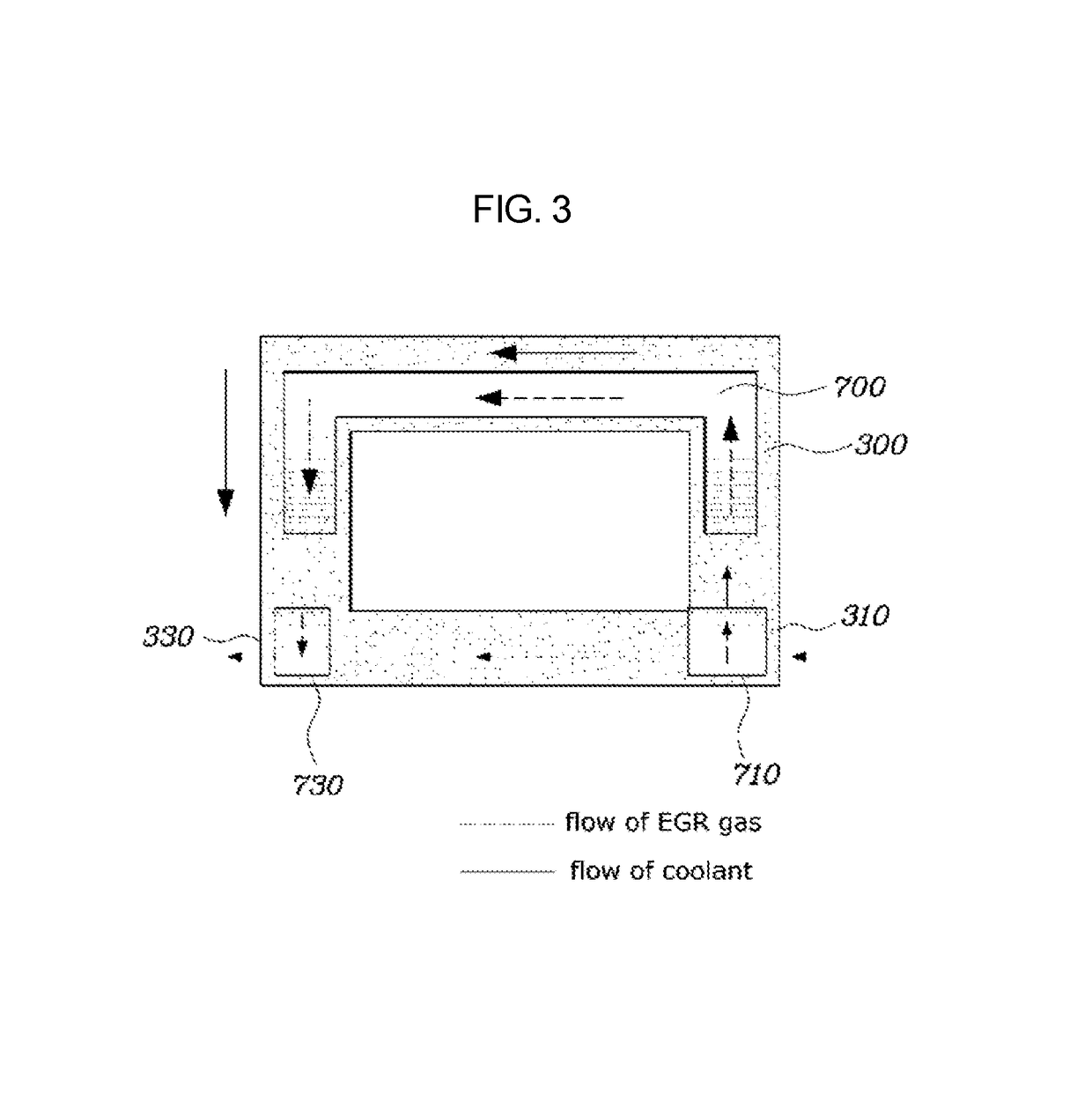
[0032]FIG. 1 is a view showing a cylinder head integrated with an exhaust manifold and an EGR cooler according to various embodiments of the present invention. FIG. 2 is a view showing the exhaust manifold 100 and the EGR cooler 700 of FIG. 1 in detail. FIG. 3 is a schematic view showing a flow of EGR gas and coolant.

[0033]Disclos...


PUM


Abstract

A cylinder head integrated with an exhaust manifold and an exhaust gas recirculation (EGR) cooler may include an exhaust manifold including a plurality of connection parts connected to a plurality of exhaust ports, respectively, and an extension part connected to a plurality of connection parts, a water jacket provided at a location adjacent to the exhaust manifold, and an EGR cooler communicating with the water jacket and configured to surround an outside of the extension part of the exhaust manifold.

Description

CROSS REFERENCE TO RELATED APPLICATION[0001]The present application claims priority to Korean Patent Application No. 10-2015-0163004, filed Nov. 20, 2015, the entire contents of which is incorporated herein for all purposes by this reference.BACKGROUND OF THE INVENTION[0002]Field of the Invention[0003]The present invention generally relates to a cylinder head integrated with an exhaust manifold and an exhaust gas recirculation (EGR) cooler in a vehicle engine, wherein the exhaust manifold and the EGR cooler are inserted into the cylinder head and are integrated with the cylinder head.[0004]Description of Related Art[0005]Generally, an exhaust manifold is developed as an additional component separately from a cylinder head and is mounted to the cylinder head, thereby frequently causing thermal damage to a vehicle as well as affecting performance and durability of an engine. Thus, the exhaust manifold has been a major issue in a vehicle package.[0006]An exhaust manifold requires a suf...

Claims


Application Information

Patent Timeline
Patent Type & Authority Patents(United States)
IPC IPC(8): F02F1/10F02M26/22F02F1/24F02M26/14F02F1/40
CPCF02F1/40F02M26/22F02M26/14F02F1/243F01N13/107F01P3/12F02M26/28F02M26/41
Inventor CHU, DONG HO
Owner HYUNDAI MOTOR CO LTD
Why Eureka
Try Eureka