Display apparatus
a technology of display apparatus and display screen, which is applied in the field of display screen, can solve the problems of increasing the price (production cost), the concern of the decrease in the accuracy of touch detection, etc., and achieves the effect of improving the accuracy
- Summary
- Abstract
- Description
- Claims
- Application Information
AI Technical Summary
Benefits of technology
Problems solved by technology
Method used
Image
Examples
first embodiment
Basic Principle of the Electromagnetic Induction System
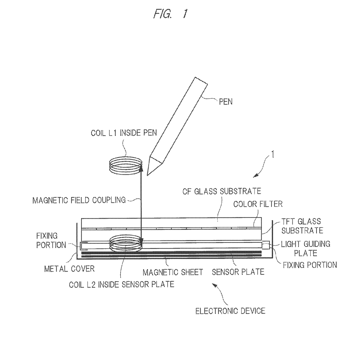
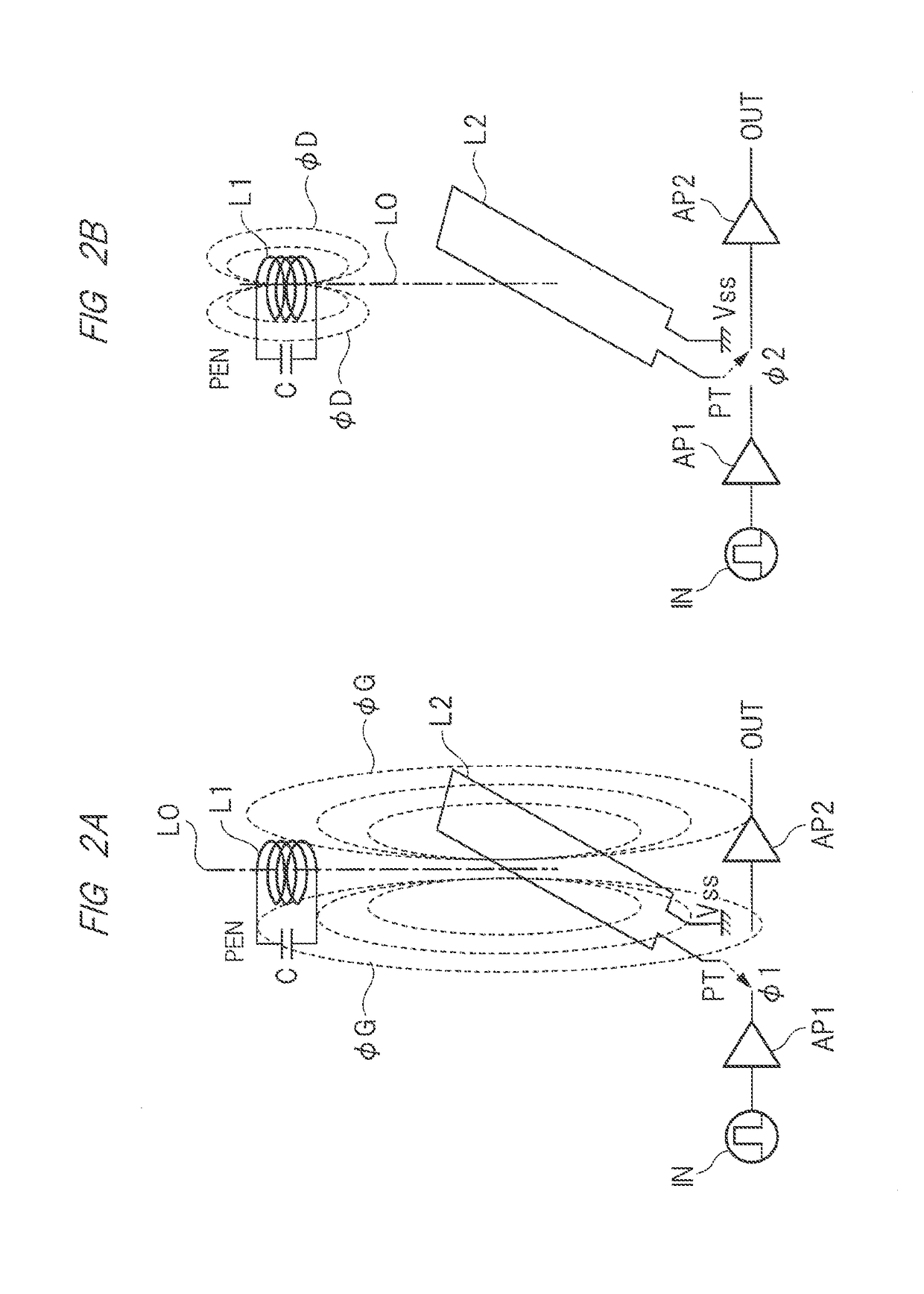
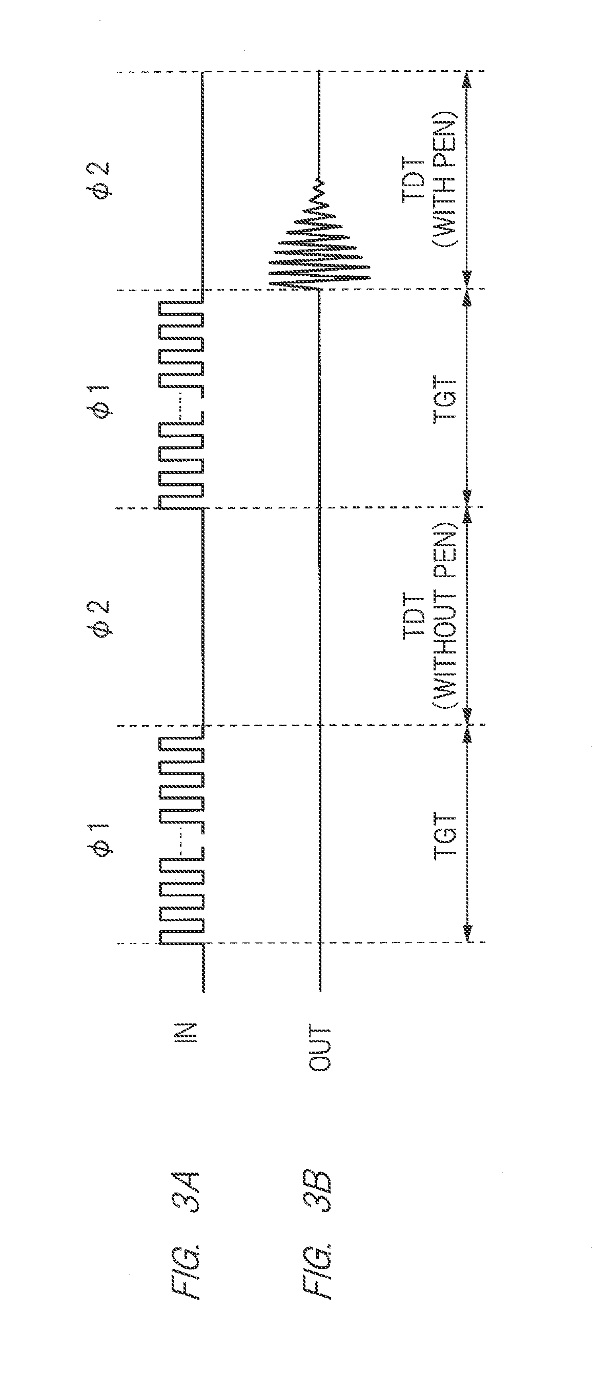
[0062]First, the basic principle of the electromagnetic induction system will be described. FIG. 1 is an explanatory diagram schematically showing the relation between a pen and an electronic device having a liquid crystal display apparatus with a touch detection function. FIGS. 2 and 3 are explanatory diagrams each schematically showing the basic principle of the electromagnetic induction system.
[0063]In FIG. 1, the electronic device includes a liquid crystal display apparatus 1 housed in a metallic cover, a light guiding plate, a sensor plate, and a magnetic sheet. In the example shown in this drawing, the sensor plate is mounted between the liquid crystal display apparatus 1 and the metallic cover. While the sensor plate is provided with a plurality of coils, FIG. 1 schematically shows one of these coils as a sensor plate internal coil (hereinafter, also simply called a coil) L2.
[0064]A coil and a capacitative element are emb...
second embodiment
[0323]FIGS. 23 and 24 are block diagrams showing the configuration of the liquid crystal display apparatus 1 according to the second embodiment. FIG. 24 continues from FIG. 23. That is, a portion indicated by a reference character DD in FIG. 23 continues to a portion indicated by a reference character DD in FIG. 24. As similar to FIG. 11, FIGS. 23 and 24 show drive electrodes TL(0) to TL(p) (first drive electrodes), a switching circuit DSC1, a selection drive electrode SDC1, and selection control circuits SR1-R, SR1-L. In FIGS. 23 and 24, TL(du1) to TL(du3) and TL(dd1) to TL(dd3) are drive electrodes for magnetic field generation (hereinafter, each of which is also called magnetic-field drive electrode (second drive electrode)) although not specifically limited.
[0324]In the first embodiment, two coils each of which is a single-winding wire are formed in the magnetic field generation period TGT, and a magnetic field is generated while two coils are set to be a unit. In the second emb...
third embodiment
[0407]FIG. 29 is an explanatory diagram showing the configuration of the liquid crystal display apparatus 1 according to the third embodiment. FIG. 29 shows an operation in touch detection. This drawing shows such a configuration as generating a magnetic field by a coil formed of drive electrodes in the magnetic field generation period TGT and as detecting a magnetic field from a pen PN by a coil formed of signal lines in the magnetic field detection period TDT.
[0408]The left side of FIG. 29 shows a state of the magnetic field generation period TGT, in which an induced voltage is generated in the coil L1 inside the pen PN shown on the upper side of FIG. 29 by a magnetic field generated in the magnetic field generation period TGT, and in which the capacitative element C (not shown) inside the pen PN is charged by the induced voltage generated in the coil L1. In the magnetic field detection period TDT, the coil L1 inside the pen PN generates a magnetic field by charges charged in the ...
PUM
 Abstract
Description
Claims
Application Information
 - R&D
- Intellectual Property
- Life Sciences
- Materials
- Tech Scout
- Unparalleled Data Quality
- Higher Quality Content
- 60% Fewer Hallucinations
Browse by: Latest US Patents, China's latest patents, Technical Efficacy Thesaurus, Application Domain, Technology Topic, Popular Technical Reports.
© 2025 PatSnap. All rights reserved.Legal|Privacy policy|Modern Slavery Act Transparency Statement|Sitemap|About US| Contact US: help@patsnap.com


