
Fingerprint based smart phone user verification

a smart phone and fingerprint technology, applied in the field of fingerprint based smart phone user verification, can solve the problems of inability to achieve optimum value, inability to provide background voice authentication, and inability to provide security in mobile electronic devices. to achieve the effect of effective and transparen

Inactive Publication Date: 2018-11-06
AMI RES & DEV
View PDF33 Cites 3 Cited by
  • Summary
  • Abstract
  • Description
  • Claims
  • Application Information

AI Technical Summary

Benefits of technology

[0013]Optional aspects of the method and system can be based on previously proven algorithms such as pattern recognition algorithm(s). They can be optionally integrated at a higher level with known Neuromorphic Parallel Processing techniques that have functionality similar to that of the biological neuron, for a multimodal fusion algorithm. For example, 1-D finger profiles may be combined with the outputs from other mobile device sensors such as audio (voice), image, or even user kinematic position stylometry (how the user typically holds the device). This provides additional modalities for authentication without increasing mobile device processing overhead as well as minimizing power consumption. These techniques can be wholly or partially implemented in remote servers accessible via wireless network(s), or in local special purpose neuromorphic procedures.

Problems solved by technology

Although there are several existing applications for mobile phones and other devices that can verify a user in order to unlock a phone, entry passwords, facial images, fingerprint “touch ID,” swipe motions or even drawing sequences are a one time entry and do not continually verify the user.
This is adequate for some applications, but not necessarily for others, such as a military use, where a device already in use could be taken from a soldier by an enemy.
Periodic user verification may be implemented with the same modality as the unlock feature, but at the expense of user productivity.
The tradeoff between longer intervals for productivity and shorter intervals for security has no realistic optimum value.
Given that these devices are typically used for computing and data communication, and not necessarily voice communication, background voice authentication is not a good omnipresent modality for this assessment.
Also, since low power usage is important for field operations, periodic or background image capture for facial image authentication expends a mobile device's battery prematurely.

Method used


Image

  • Fingerprint based smart phone user verification
  • Fingerprint based smart phone user verification
  • Fingerprint based smart phone user verification

Examples


Embodiment Construction

A. Introduction

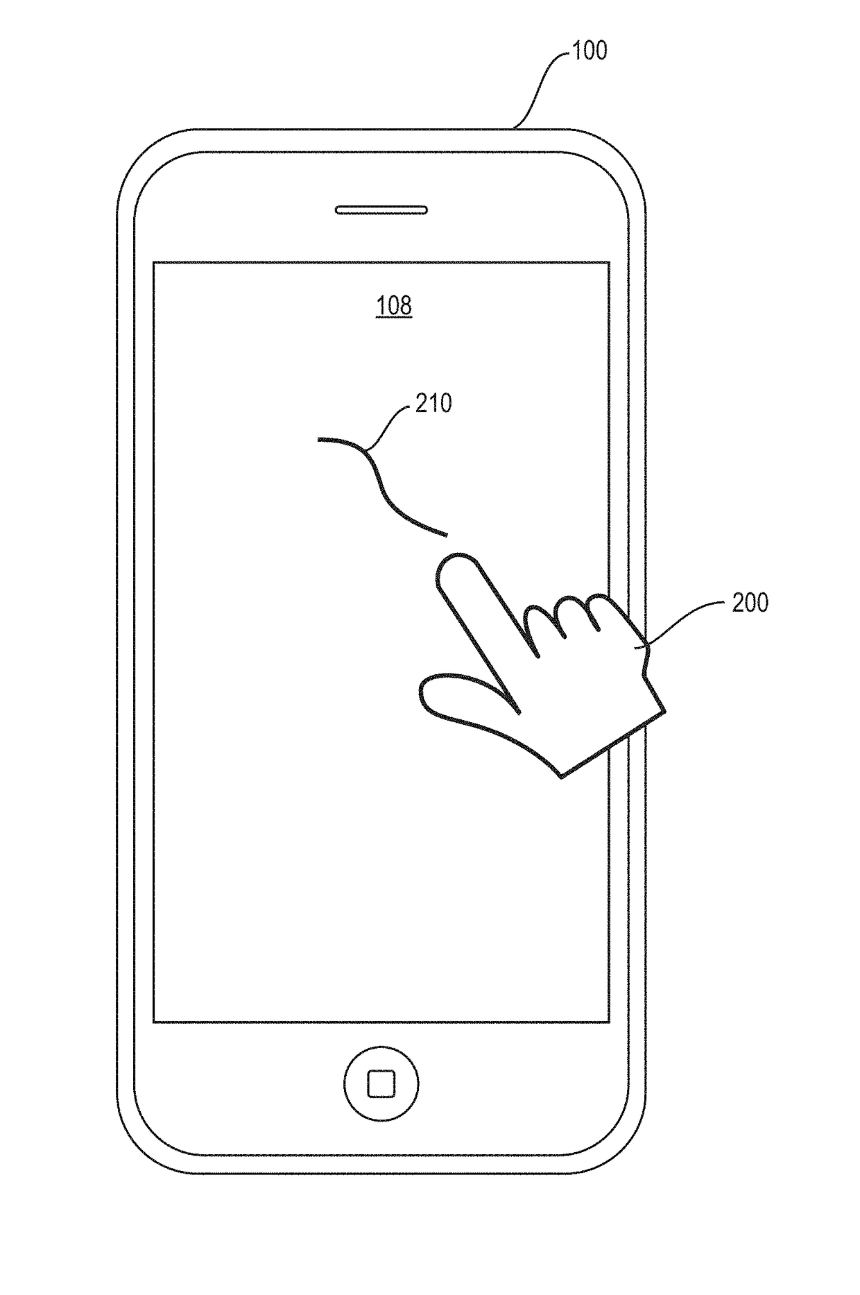
[0035]Described below are a system and method for using a touch screen, already present in most mobile devices, to provide active, continuous user authentication. The touch screen inputs provided as a user goes about normal interaction with the device provide sufficient interaction to verify that a valid user has possession of the device. The same physiological data can be combined with habitual gestures detected using the same touchscreen sensors to further authenticate the user.

B. Typical Device Architecture

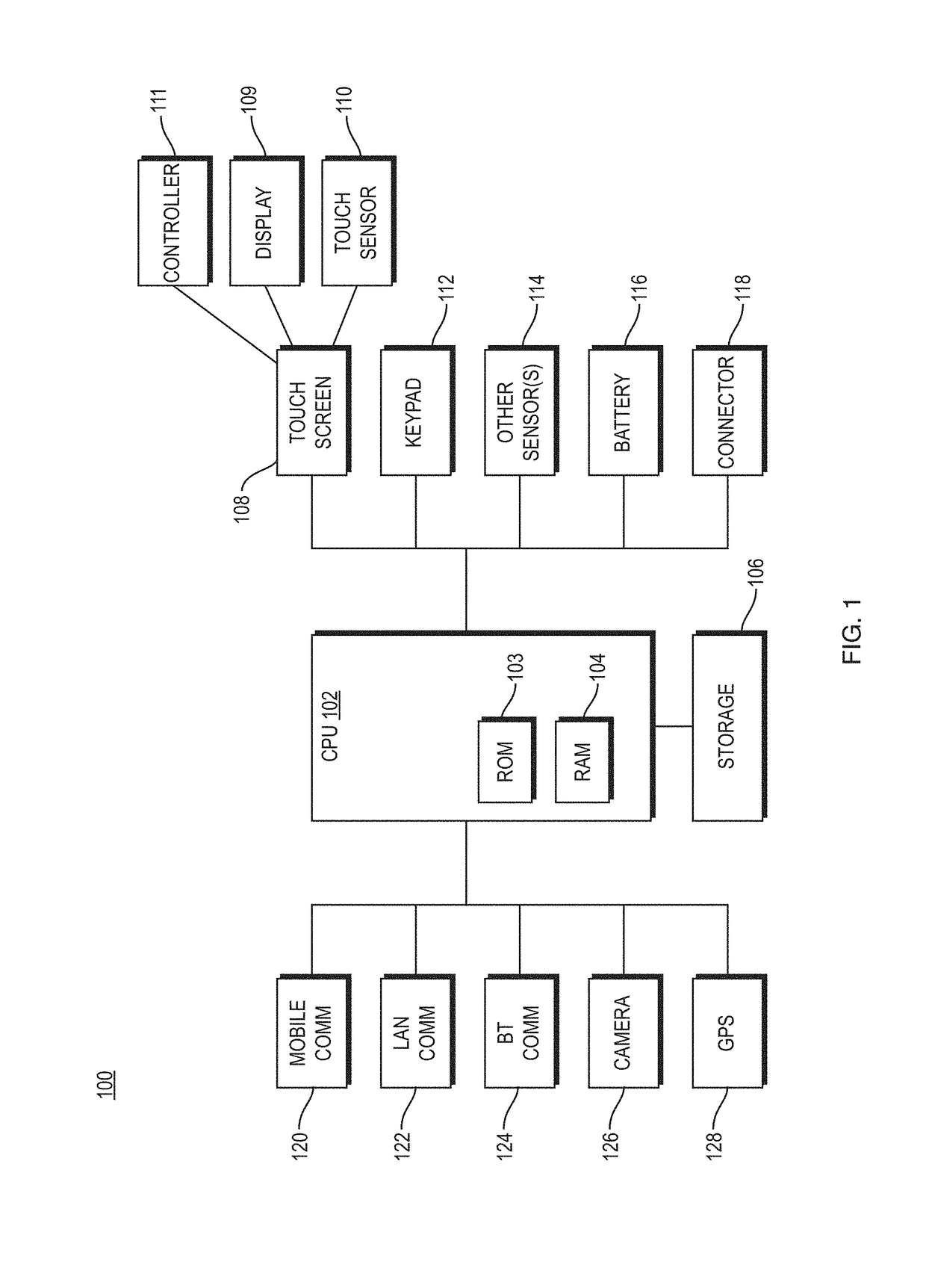
[0036]FIG. 1 is a high-level block diagram of a typical device in which the methods and systems described herein may be implemented in whole or in part. Those of skill in the art will recognize the block diagram as illustrating example components of a typical smartphone, tablet, laptop computer device 100, or the like. The device 100 includes a central processing unit (CPU) 102 which may be a integrated circuit microprocessor or microcontroller. CPU 102 includes ...


PUM


Abstract

A touchscreen, now incorporated in most smartphones, tablets, laptops, and similar devices, presents an effective and transparent method to incorporate continuous active user verification schemes. The touchscreen element grid structure can be used to capture information, such as a set of one-dimensional time-varying signals produced as the user's finger moves past the grid intersections points. This information may be used to verify the user, or that a valid user currently has possession of the mobile device, even while the user is not consciously engaged in an active verification process. Further functions, such as habitual gesture recognition, can also be performed using the same grid outputs.

Description

CROSS REFERENCE TO RELATED APPLICATIONS[0001]This application claims the benefit of a U.S. Provisional Patent Application Ser. No. 62 / 293,924 filed Feb. 11, 2016 entitled “Fingerprint Based User Verification Using Self Registration of the Valid User” and is a continuation in part of co-pending U.S. patent application Ser. No. 15 / 226,153 filed Aug. 2, 2016 entitled “Fingerprint Based Smart Phone User Verification” which is a continuation in part of co-pending U.S. patent application Ser. No. 14 / 231,935 filed Apr. 1, 2014 entitled “Fingerprint Based Smartphone User Verification”, which in turn claims the benefit of U.S. Provisional Patent Application Ser. No. 61 / 807,113 filed Apr. 1, 2013 entitled “Fingerprint Based Smart Phone User Verification”. The entire contents of each of the above-referenced patent applications are hereby incorporated by reference.BACKGROUNDTechnical Field[0002]This application relates in general to providing security in mobile electronic devices and in particu...

Claims


Application Information

Patent Timeline
Patent Type & Authority Patents(United States)
IPC IPC(8): G06K9/00G06F3/0488H04M1/673G06F3/044H04W12/06H04L29/06G06K9/22G06F21/32H04W88/02
CPCG06K9/00026G06F3/0488G06F21/32G06K9/001G06K9/0002G06K9/0008G06K9/00355G06K9/00892G06K9/22H04L63/0861H04M1/673H04W12/06G06F3/044H05K999/99G06F2203/0338G06F2221/2139H04M2250/22H04W88/02H04W12/68H04W12/065G06V40/1335G06V40/1359G06V40/1376G06V40/1306G06V40/28G06V40/70G06V10/17
Inventor APOSTOLOS, JOHN T.MOUYOS, WILLIAMFENG, JUDYJEFFREY, DWAYNE T.DOBROWOLSKI, LILLIAN
Owner AMI RES & DEV
Learn More