Fuel cell vehicle

a fuel cell and vehicle technology, applied in the direction of battery/cell propulsion, electric propulsion mounting, transportation and packaging, etc., can solve the problems of increased surface pressure applied from the tank, large volume of high-pressure pipes, and high cost, so as to reduce the size of the driving mechanism, shorten the distance over which power is transferred, and reduce the possibility

Active Publication Date: 2018-09-25
TOYOTA JIDOSHA KK
View PDF15 Cites 4 Cited by
  • Summary
  • Abstract
  • Description
  • Claims
  • Application Information

AI Technical Summary

Benefits of technology

[0007]However, a pressure-reducing valve is disposed between tanks in order to reduce the pipe length of a fuel supply pipe extending from the tanks to the pressure-reducing valve, in some cases. In this case, in the event of a frontal collision or a rear-end collision of a vehicle, the pressure-reducing valve may be damaged due to an impact. In particular, when the tanks are disposed such that the longitudinal direction of the tanks coincides with the vehicle front-rear direction, the surface pressure applied from the tanks increases, and thus the possibility that the pressure-reducing valve will be damaged increases.
[0008]The disclosure provides a fuel cell vehicle configured to reduce the possibility that a pressure-reducing valve will be damaged in the event of, for example, a frontal collision or a rear-end collision of the vehicle.

Problems solved by technology

Because the high-pressure pipe needs to have a high strength, the high-pressure pipe is large in volume and involves a high cost.
In this case, in the event of a frontal collision or a rear-end collision of a vehicle, the pressure-reducing valve may be damaged due to an impact.
In particular, when the tanks are disposed such that the longitudinal direction of the tanks coincides with the vehicle front-rear direction, the surface pressure applied from the tanks increases, and thus the possibility that the pressure-reducing valve will be damaged increases.

Method used


Image

  • Fuel cell vehicle
  • Fuel cell vehicle
  • Fuel cell vehicle

Examples


Embodiment Construction

[0031]Hereinafter, the configuration of a fuel cell vehicle according to an example embodiment of the disclosure will be described in detail with reference to the accompanying drawings.

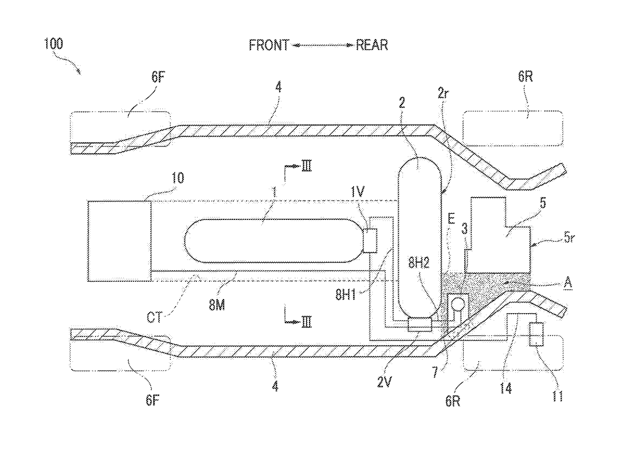
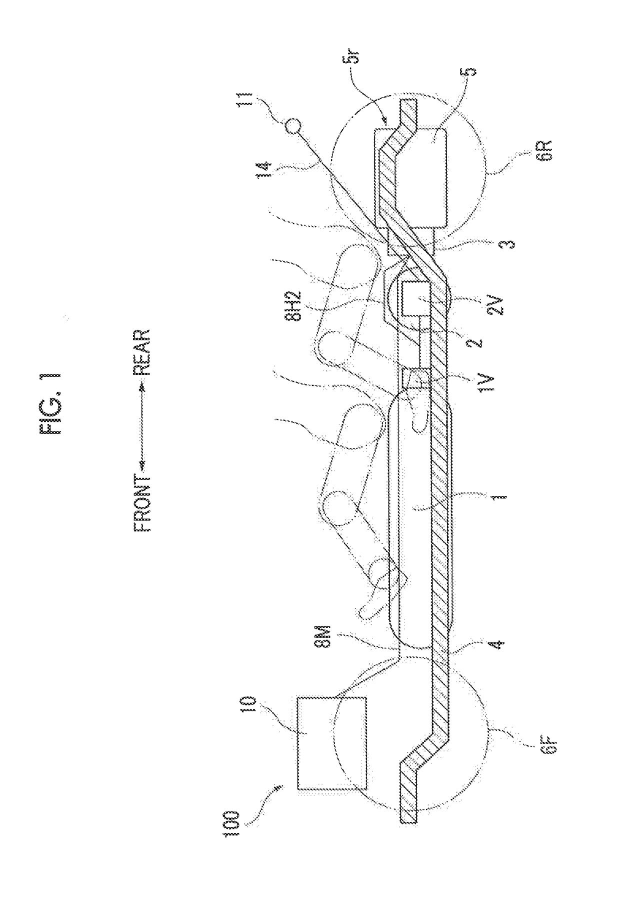
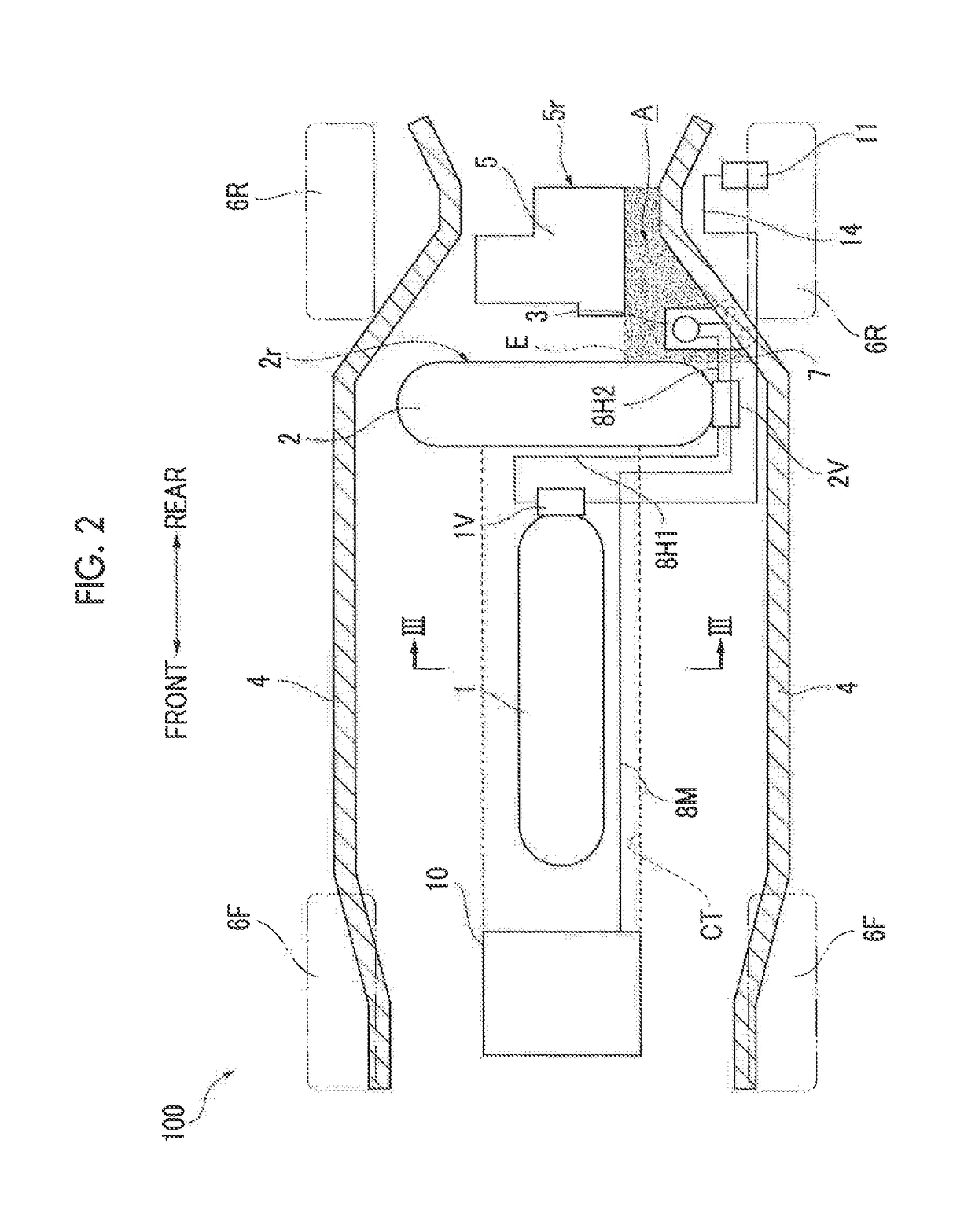
[0032]A fuel cell vehicle 100 according to the present embodiment is a rear-wheel drive vehicle. The fuel cell vehicle 100 includes a front tank 1, a rear tank 2, a pressure-reducing valve 3, side members 4, a motor 5, wheels (front wheels 6F and rear wheels 6R), a fuel cell 10, and so forth.

[0033]The front tank 1 and the rear tank 2 are containers to be filled with hydrogen gas used as fuel. In the fuel cell vehicle 100 according to the present embodiment, the front tank 1 is disposed longitudinally at a position in a center tunnel CT under a floor panel FP such that the longitudinal direction of the front tank 1 coincides with the vehicle front-rear direction (the forward-backward traveling direction) (refer to FIG. 2 and FIG. 3). The rear tank 2 is transversely disposed at a position rearward of th...


PUM


Abstract

A fuel cell vehicle includes a first tank, a second tank, first and second valves for releasing gas, a gas passage for supplying gas to a fuel cell via the first and second valves, a pressure-reducing valve for decompressing the gas, side members disposed on the respective sides of the vehicle, and a motor disposed rearward of the second tank and configured to drive wheels. The first tank is not disposed downstream of the second tank, on the gas passage. The pressure-reducing valve is disposed in a region located rearward of a rear end of the second tank in a vehicle front-rear direction, forward of a rear end of the motor in the vehicle front-rear direction, and between one of the side members and an extended line extended in the vehicle front-rear direction from a side wall of the motor. The pressure-reducing valve is disposed on the second valve side.

Description

INCORPORATION BY REFERENCE[0001]The disclosure of Japanese Patent Application No. 2016-031289 filed on Feb. 22, 2016 including the specification, drawings and abstract is incorporated herein by reference in its entirety.BACKGROUND[0002]1. Technical Field[0003]The disclosure relates to a fuel cell vehicle.[0004]2. Description of Related Art[0005]For example, German Patent Application Publication No. 102009039079 (DE 102009039079 A1) describes a fuel cell vehicle including a first tank, a second tank, and a motor. The first tank storing hydrogen fuel is disposed such that the longitudinal direction of the first tank coincides with the vehicle front-rear direction. The second tank is disposed rearward of the first tank such that the longitudinal direction of the second tank coincides with the vehicle transverse direction (i.e., vehicle right-left direction). In addition, a motor is disposed rearward of the second tank.[0006]In addition, a fuel cell vehicle is provided with a pressure-r...

Claims


Application Information

Patent Timeline
Patent Type & Authority Patents(United States)
IPC IPC(8): B60K15/03B60K15/07B60K15/063B60L11/18B60K1/00
CPCB60K15/03006B60K1/00B60K15/063B60K15/07B60L11/1881B60K2001/001B60K2015/0635B60K2015/03144B60K2015/03296B60K2015/03315B60K2015/03328B60K2015/0633B60K2015/0634B60K2015/03026B60L50/71Y02T90/40
Inventor OKAWACHI, EIJI
Owner TOYOTA JIDOSHA KK
Why Eureka
Try Eureka