Heat pipe type buried pipe heat-exchanging device

A tube heat exchange and heat pipe type technology, which is applied in the field of heat pipe type buried pipe heat exchange devices, can solve the problems of large pump power consumption, large flow resistance of circulating fluid, long buried pipe length, etc., and achieves high heat exchange efficiency and reduced Fluid flow resistance, the effect of reducing power consumption

Inactive Publication Date: 2012-07-04
YIKEBO ENERGY TECH SHANGHAI
View PDF4 Cites 3 Cited by
  • Summary
  • Abstract
  • Description
  • Claims
  • Application Information

AI Technical Summary

Problems solved by technology

[0007] The purpose of the present invention is to provide a heat pipe type buried pipe heat exchange device to overcome the problems of long buried pipe length, large circulating fluid flow resistance and large pump power consumption in the existing soft heat exchange device

Method used


Image

  • Heat pipe type buried pipe heat-exchanging device
  • Heat pipe type buried pipe heat-exchanging device
  • Heat pipe type buried pipe heat-exchanging device

Examples


Embodiment Construction

[0016] The specific embodiments of the present invention will be described in detail below in conjunction with the accompanying drawings.

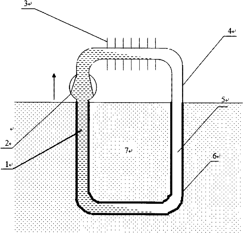
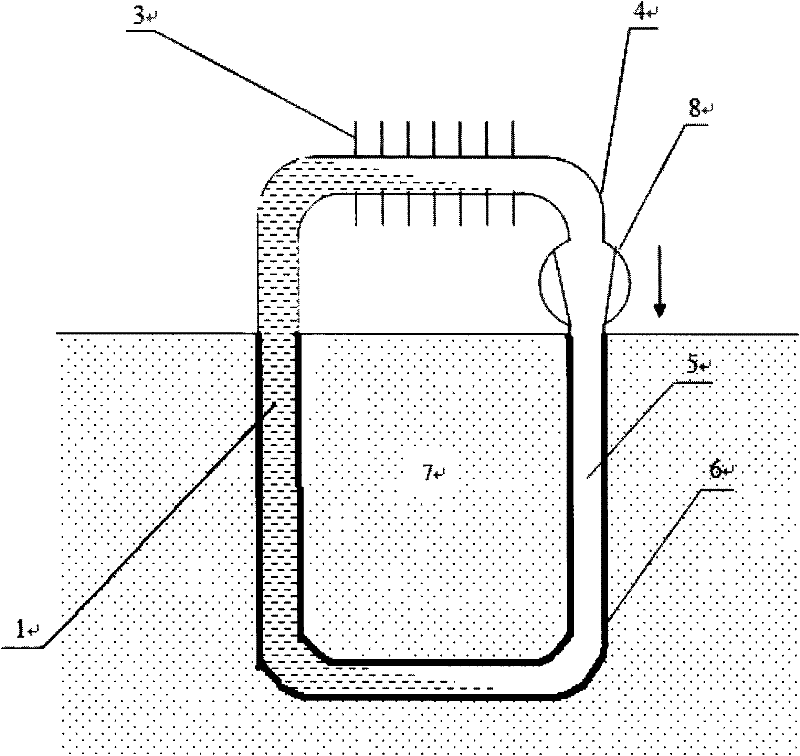
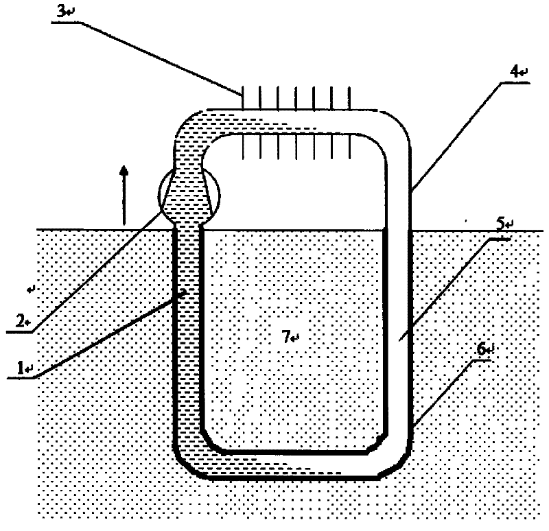
[0017] First, please refer to figure 1 , figure 1 It is a structural schematic diagram of the first embodiment of the heat pipe type buried pipe heat exchange device of the present invention, as attached figure 1 As shown, the present invention includes liquid phase change working medium 1 (gas phase change working medium 5 ), liquid phase driving device 2 (gas phase driving device 8 ), metal fins 3 , metal pipeline 4 , and plastic pipeline 6 . Plastic pipeline 6 is positioned at vertical direction, is buried in the soil. Metal fins 3 are provided on the heat exchange part between the metal pipeline 4 and the fluid medium to increase the heat exchange area. The liquid phase driving device 2 is arranged on the part of the liquid phase change working medium 1 in the metal pipeline 4 . The gas-phase driving device 8 is arranged on the gas...


PUM


Abstract

The invention provides a heat pipe type buried pipe heat-exchanging device. The device comprises a first pipe, a second pipe and a driving device, wherein a heat pipe of the first pipe is made of plastic, and the first pipe is buried in soil to exchange heat with the soil; the heat pipe of the second pipe is made of a metal, the two ends of the second pipe are connected with the two ends of the first pipe, and the second pipe is exposed in air; and the driving device is arranged in the second pipe. The heat exchanging efficiency between an ordinary plastic pipe and the soil is improved by phase-change heat transfer, the length of the buried pipe is reduced, the flow resistance of fluid is reduced, and then the power consumption of a heat-exchanging system pump is effectively reduced.

Description

technical field [0001] The invention belongs to heat exchange equipment, and in particular relates to a heat pipe type buried pipe heat exchange device, which is suitable for fields such as underground buried pipe heat exchange systems of ground source heat pumps and underground building air conditioning systems where geothermal resources can be utilized. Background technique [0002] A heat pump is a device that makes heat flow from a low-temperature medium to a high-temperature medium through a refrigeration cycle. [0003] Ground source heat pump is a high-efficiency energy-saving air-conditioning system that can supply heat and cool by using the solar energy and geothermal energy absorbed in the shallow water source on the earth's surface and the soil, and adopts the principle of heat pump. The surface soil and water body is a huge solar heat collector, which collects 47% of the solar radiation energy, which is more than 500 times that humans use every year; at the same ...

Claims


Application Information

Patent Timeline
Patent Type & Authority Applications(China)
IPC IPC(8): F28D15/02F28F21/06F28F21/08
CPCY02E10/16F28F21/062F28D15/0266F24J3/086F24T10/40Y02E10/10
Inventor 项晓东张琛
Owner YIKEBO ENERGY TECH SHANGHAI
Why Eureka
Try Eureka