Inflator assembly

a technology of inflator and assembly, which is applied in the direction of vehicle safety belts, vehicle components, belt control systems, etc., can solve the problems of inflator assembly, large time and labor costs, and need to machining the duct (pipe) to achieve the effect of reducing the connection margin between the pipe and the inflator casing, reducing the time and labor costs, and facilitating formation

Inactive Publication Date: 2005-04-26
JOYSON SAFETY SYST JAPAN KK
View PDF17 Cites 3 Cited by
  • Summary
  • Abstract
  • Description
  • Claims
  • Application Information

AI Technical Summary

Benefits of technology

[0021]Since the pipe holding plate is clamped and fixed between the first flange and the second flange formed in the periphery of the pipe so as to unite them, the connection margin between the bracket and the pipe can be significantly reduced, thus enabling the entire length of the pipe to be significantly shortened. Therefore, the entire length of the inflator assembly can be also significantly shortened.
[0038]According to this structure, since the first and second pipe holding plates with the spacer therebetween are clamped and fixed between the front end of the inflator casing and the flange formed in the periphery of the pipe to unite them, the pipe can be held by the pair of pipe holding plates and the spacer ring with very high stability without increasing the connection margin between the pipe and the bracket.

Problems solved by technology

The inflator assembly has another disadvantage in that a lot of time and labor are needed for machining the duct (pipe) 30 to form threaded portions to be screwed into the duct connecting portion 39 of the inflator holder 28 and the rear end portion of the piston holder 32 or for welding after the rear end portion and the front end portion of the duct (pipe) 30 are inserted into the duct connecting portion 39 and the rear end portion of the piston holder 32, respectively.

Method used


Image

  • Inflator assembly
  • Inflator assembly
  • Inflator assembly

Examples


Embodiment Construction

[0057]Embodiments of the present invention will be described below with reference to the accompanying drawings.

[0058]In the following description, “front side” means the downstream side of gas flow from the inflator, and “rear side” means the upstream side of the gas flow.

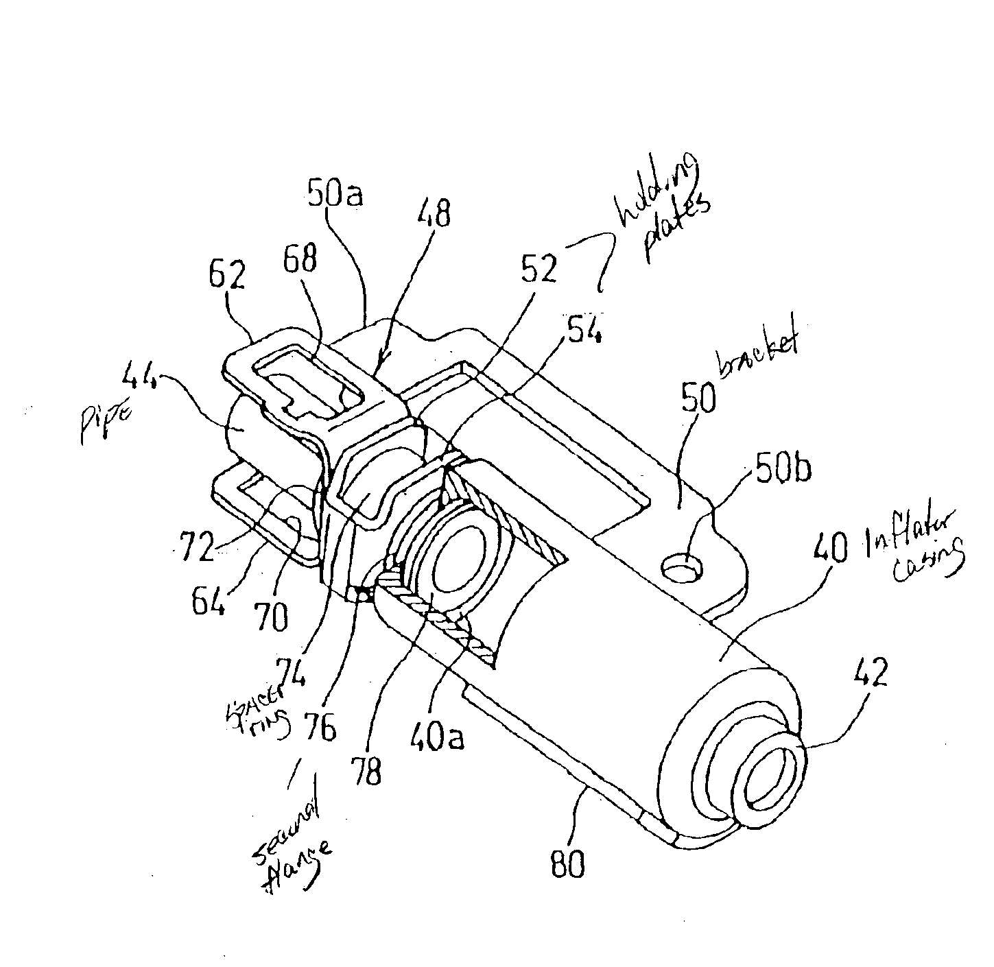
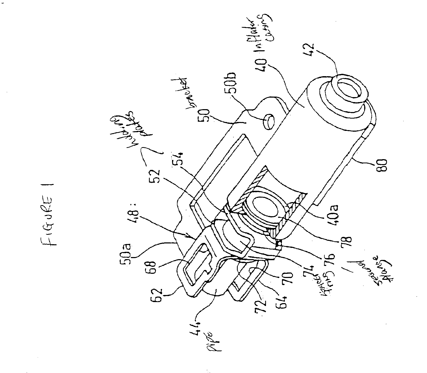
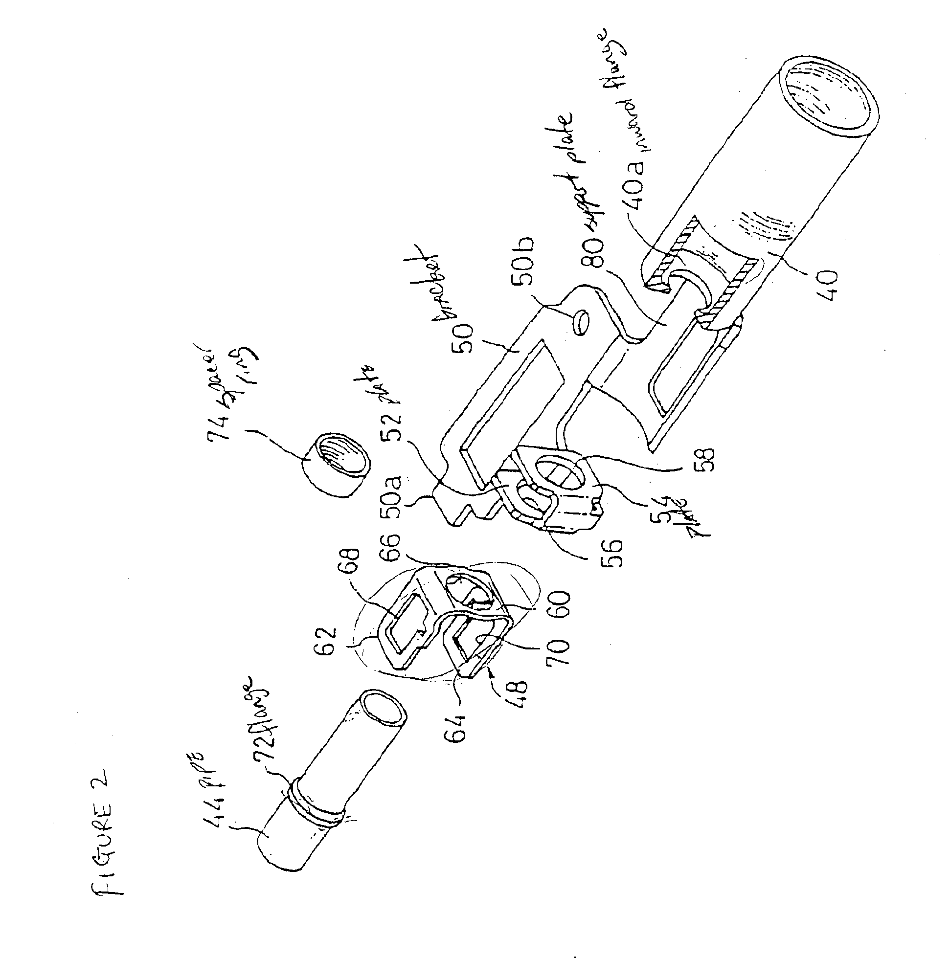
[0059]The inflator assembly comprises a cylindrical inflator casing 40 formed with an inward flange 40a in the inner periphery of a front end portion thereof, an initiator 42 for igniting gas generant accommodated in the inflator casing 40, a pipe (duct) 44 connected to the front end portion of the inflator casing 40, a piston holder 48 for holding a piston 46 (FIG. 8) on the front end portion of the pipe 44, and a plate-like bracket 50 for connecting the above components in a lump to a buckle 4A (FIG. 8, FIG. 9(a)). The inflator casing 40 and the pipe 44 are arranged coaxially with each other along the side of the bracket 50.

[0060]The inflator casing 40, the gas generant accommodated in the inflator casing 40, and...


PUM


Abstract

An inflator assembly that has a shorter entire length and can be manufactured easily. The inflator assembly includes a pipe, a piston holder, first and second pipe holding plates, a bracket, and an inflator casing. The pipe is inserted through a pipe through hole in the base of the piston holder, through pipe through holes in the pipe holding plates, and through a spacer ring. The base of the piston holder, the spacer ring, and the pipe holding plates are clamped together between first and second flanges of the pipe. The inflator casing is fitted around the outer periphery of a rear end portions of the pipe and has an inward flange that is clamped and fixed between the first and second flanges of the pipe. Second and third flanges are formed by deforming portions of the pipe to have a larger diameter.

Description

BACKGROUND[0001]The present invention relates to an inflator assembly that can be suitably adapted to a buckle of an inflatable belt device for protecting an occupant of a vehicle, such as an automobile, in the event of a vehicle collision. Such a device is the subject of Japanese Patent Application No. 2001-375950, filed Dec. 10, 2001, and Japanese Patent Application No. 2002-305985, filed Oct. 21, 2002, both of which are hereby incorporated by reference.[0002]A conventional example of a buckle of an inflatable belt device is disclosed in Japanese Unexamined Patent Application Publication No. H 11-334513 (incorporated by reference herein) and is explained below with reference to FIGS. 10(a), 10(b), and 11. FIG. 10(a) is a front view showing a tongue and a buckle of an inflatable belt device according to the conventional example, and FIG. 10(b) is a perspective view of the buckle. FIG. 11 is a structural illustration without an outer shell showing the state where the tongue is latch...

Claims


Application Information

Patent Timeline
IPC IPC(8): B60R21/26B60R21/18B60R21/16B60R22/14B60R21/264
CPCB60R21/18B60R21/26B60R2021/2612
Inventor SUYAMA, YOJIISEKI, HIDEO
Owner JOYSON SAFETY SYST JAPAN KK
Why Eureka
Try Eureka