
Signal amplification circuit

a signal amplification and circuit technology, applied in the field of signal processing, can solve the problems of low output dynamic range, low output accuracy, and high noise of low frequencies, and achieve the effects of low bandwidth, low power consumption, and flexible bandwidth control

Active Publication Date: 2018-09-18
CSMC TECH FAB2 CO LTD
View PDF10 Cites 0 Cited by
  • Summary
  • Abstract
  • Description
  • Claims
  • Application Information

AI Technical Summary

Benefits of technology

[0008]Accordingly, it is necessary to provide a signal amplification circuit with small circuit area, low power consumption, good noise suppression and variable gain.
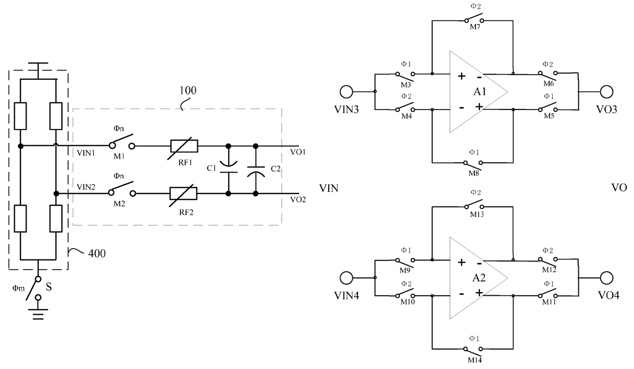
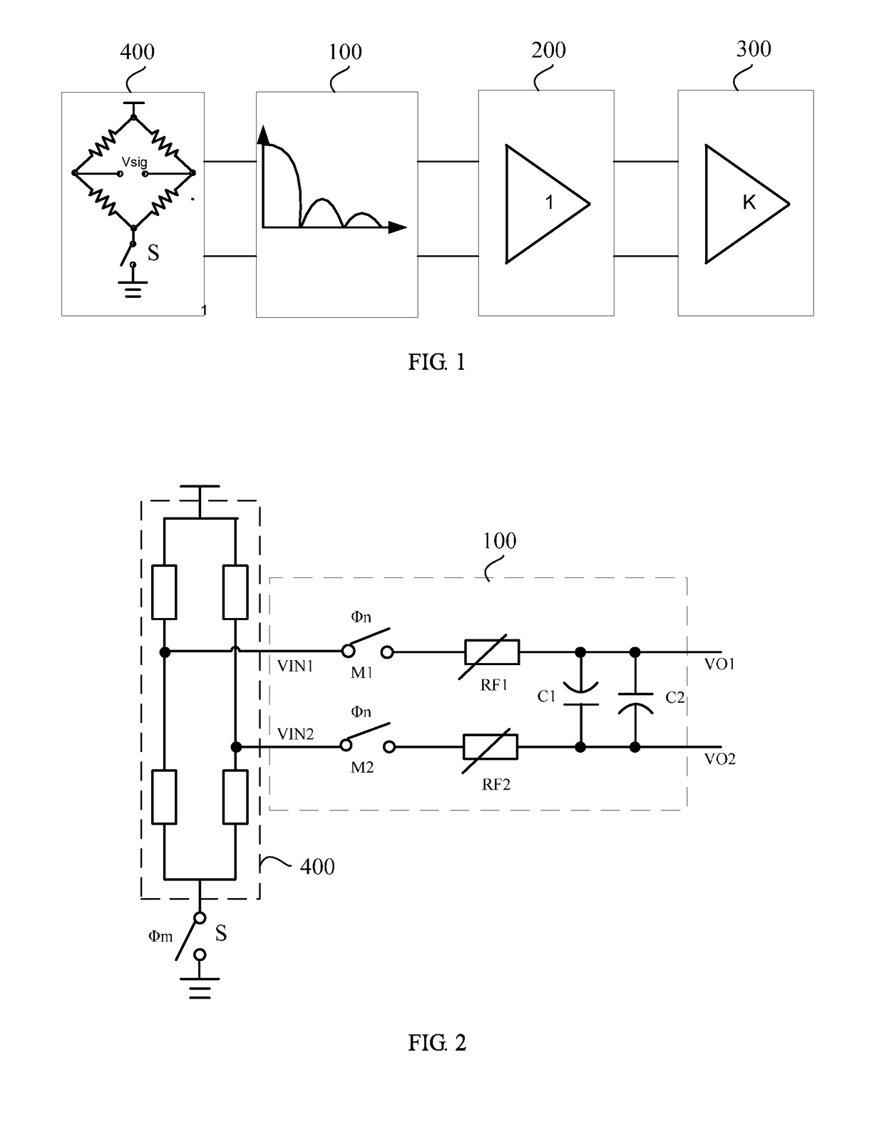
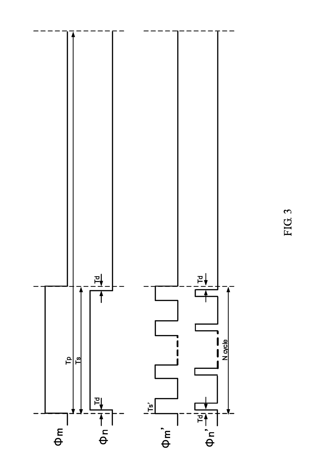
[0014]The aforementioned signal amplification circuit can divide the operation state of the circuit by controlling switch signals, and the opening or closing of the first switch and the second switch, such that the power consumption is reduced, with same sizes of resistors and capacitors a low bandwidth is achieved, and not only is the bandwidth flexible to control, while an area and power consumption are reduced, but also the noise suppression is better. Choosing an adjustable resistor and increasing a bandwidth adjustable range make the signal amplification circuit have enough resolution for small signals of different ranges. The first capacitor and the second capacitor are connected between the first output terminal and the second output terminal, respectively, with their polarity opposite to each other, thus noise introduced into a layout design can be effectively suppressed.

Problems solved by technology

And if it is directly inputted into an analog-to-digital circuit (ADC), then a dynamic range of an output will be low, and an accuracy of the output declines.
Noise of a harmonic frequency of a control clock signal is introduced into the system, meanwhile, there is much noise of low frequencies in the environment (for example, a sound signal), if not filtered, a detected acceleration signal will be affected.
If a filter circuit is introduced, resistors and capacitors applied to a filter capacitor will lead to an oversized a chip.
A sensor is in a working state all through a signal processing process, which results in a great power consumption.
The front-end amplification circuit does not remove low-frequency 1 / f noise or an input offset voltage, or use a buffer circuit having a large capacitor and based on Auto-Zero technology and correlated double sampling (CDS), which results in a large area of the circuit, and makes the circuit not easy to be integrated.
The amplification circuit has a fixed gain, such that for different ranges of sensors, resolution for small signals is not enough.

Method used


Image

  • Signal amplification circuit
  • Signal amplification circuit
  • Signal amplification circuit

Examples


Embodiment Construction

[0028]Embodiments of the disclosure are described more fully hereinafter with reference to the accompanying drawings. The various embodiments of the disclosure may, however, be embodied in many different forms and should not be construed as limited to the embodiments set forth herein. Rather, these embodiments are provided so that this disclosure will be thorough and complete, and will fully convey the scope of the disclosure to those skilled in the art.

[0029]Unless otherwise defined, all terms (including technical and scientific terms) used herein have the same meaning as commonly understood by one of ordinary skill in the art to which this disclosure belongs. The terms used herein in the specification of the present disclosure are for the purpose of describing the embodiments only and are not intended to limit the invention. As used herein, the term “and / or” includes any and all combinations of one or more of the associated listed items.

[0030]In the following descriptions, all swi...


PUM


Abstract

A signal amplification circuit comprises a low pass filter circuit (100). The low pass filter circuit (100) comprises two input ends and two output ends and further comprises two capacitors (C1, C2) having opposite polarities respectively connected between two output ends. A buffer circuit (200) comprises two input ends, a first operational amplifier (A1) and a second operational amplifier (A2), two output ends and a plurality of switches. A switched capacitor integrated circuit (300) comprises two input ends, a third operational amplifier (A3), a plurality of capacitor modules, a plurality of chopper modulators and two output ends. A signal switch (S) is used to control the on and off states of voltage signal before amplification.

Description

CROSS REFERENCE TO RELATED APPLICATIONS[0001]This application is a National Phase filing under 35 U.S.C. § 371 of PCT / CN2016 / 072813 filed on Jan. 29, 2016 and this application claims priority to Chinese Application No. 201510171099.6 filed on Apr. 10, 2015 under 35 U.S.C. § 119. The entire contents of each application are hereby incorporated by reference.FIELD OF THE INVENTION[0002]The present disclosure relates to the field of signal processing, and particularly relates to a signal amplification circuit.BACKGROUND OF THE INVENTION[0003]A micro-electro-mechanical system (MEMS) accelerometer is an accelerometer fabricated using MEMS technology. With advantages such as small size, light weight, and low power consumption, the MEMS accelerometer is widely applied to vibration detection, azimuth detection, consumer application, motion recognition, and other fields.[0004]A piezoresistive accelerometer is fabricated using the piezoelectric effect of lead zirconate titanate (PZT). When the ...

Claims


Application Information

Patent Timeline
Patent Type & Authority Patents(United States)
IPC IPC(8): H03F3/45H03F1/26
CPCH03F1/26H03F3/45475H03F2203/45514H03F2200/165H03F3/387H03F2203/45551
Inventor WANG, XUEYANZHANG, WEIYANCHEN, QIANG
Owner CSMC TECH FAB2 CO LTD
Learn More