Coil assembly for accurate adjustment of magic angle in solid-state NMR apparatus and method of adjusting magic angle using such coil assembly

a coil assembly and magic angle technology, applied in the field of coil assembly of solid-state nmr apparatus, can solve the problems of high resolution not being achieved, setting accuracy not always satisfactory, error effects, etc., and achieve the effect of minimizing the effect of resolution on nmr resonance lines, and avoiding increases in linewidths

Active Publication Date: 2018-08-14
JEOL LTD
View PDF4 Cites 4 Cited by
  • Summary
  • Abstract
  • Description
  • Claims
  • Application Information

AI Technical Summary

Benefits of technology

[0026](1) According to the first embodiment set forth in (A1) above, the length and diameter defining the shape of the Helmholtz saddle coils used as a coil assembly for accurate adjustment of the magic angle are so chosen as to satisfy the relationship, 1.91≤2L (length) / 2a (diameter)≤2.15. As a result, a coil assembly for accurate adjustment of the magic angle can be provided which avoids increases in linewidths and can minimize the effects on the resolution of NMR resonance lines.
[0027](2) According to the embodiment set forth in (A2) above, the length and diameter defining the shape of the Helmholtz saddle coils used as a coil assembly for accurate adjustment of the magic angle are so chosen as to satisfy the relationship, 1.99≤2L (length) / 2a (diameter)≤2.02. As a result, a coil assembly for accurate adjustment of the magic angle can be provided which avoids increases in linewidths and can minimize the effects on the resolution of NMR resonance lines.
[0028](3) The embodiments set forth respectively in (A3) and (A4) provide a method of adjusting the magic angle, the method being implemented in a solid-state NMR apparatus equipped with a coil assembly according to (A1) for accurate adjustment of the magic angle. This method can determine an optimum current supplied into the coil assembly for accurate adjustment of the magic angle.

Problems solved by technology

Thus, high resolution is not achieved.
However, the setting accuracy has not been always satisfactory for the following reason.
Each component constituting the angle varying mechanism is segmented into parts and so error effects caused by deformations of the individual parts and backlash of toothed wheels will overlap.
Therefore, it has been difficult to set the angle at an accuracy of, for example, within 0.001°.

Method used


Image

  • Coil assembly for accurate adjustment of magic angle in solid-state NMR apparatus and method of adjusting magic angle using such coil assembly
  • Coil assembly for accurate adjustment of magic angle in solid-state NMR apparatus and method of adjusting magic angle using such coil assembly
  • Coil assembly for accurate adjustment of magic angle in solid-state NMR apparatus and method of adjusting magic angle using such coil assembly

Examples


example

[0120]An X0 shim coil was created based on the optimum range derived by us as described in this way. The shape of this shim coil alone is shown in FIG. 14. FIG. 15 is a photograph showing a state in which the shim coil has been mounted to a retainer for a wide bore magnet.

[0121]The coil has dimensions and shape as described below.

[0122]conductor line material: coated rectangular copper wire having a width of 2.6 mm and a thickness of 0.3 mm, coil diameter (inside diameter 2a) of 66.3 mm, coil height (2L) ranging from a maximum height of 157.2 mm (outermost turn) to a minimum height of 123.6 mm (innermost turn)

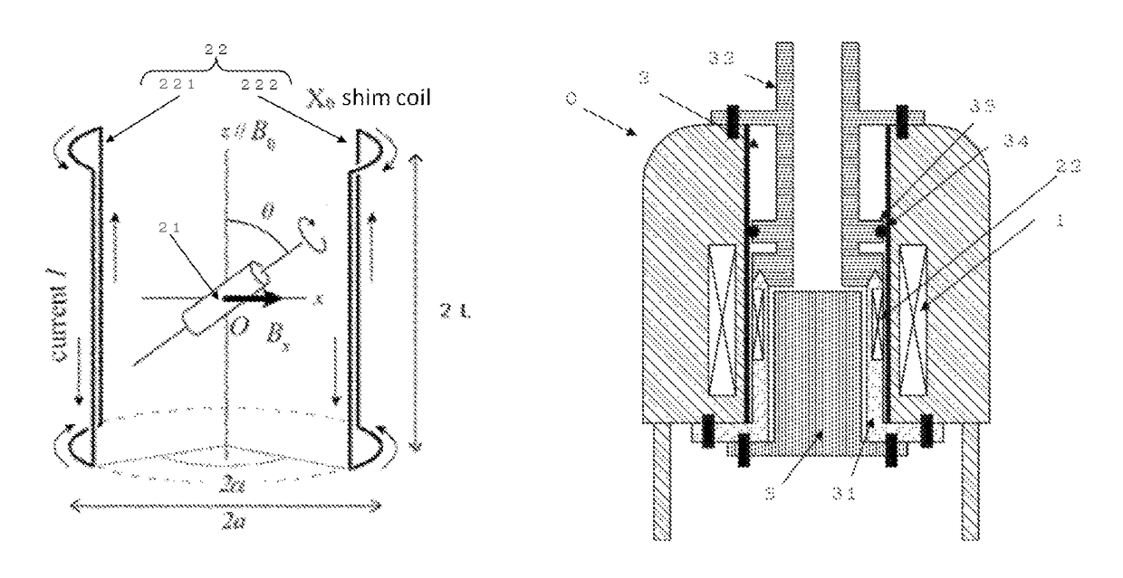
[0123]angular aperture (2α) ranging from a maximum value of 70° (innermost turn) to a minimum value of 10° (outermost turn)

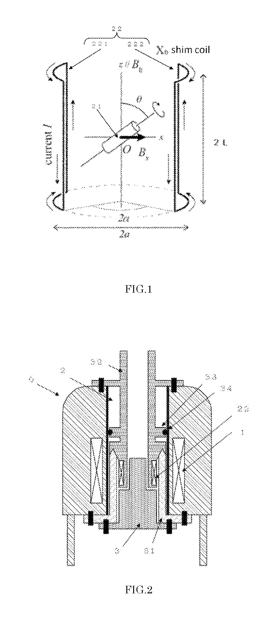
[0124]The set of equipment of FIG. 15 was inserted from the top bore opening end of the superconducting magnet to place the X0 shim coil into the center of the magnetic field. Furthermore, an NMR probe (MAS probe) was inserted from the bottom of the magnet ...


PUM


Abstract

A specially shaped coil assembly for accurate adjustment of the magic angle is provided to permit accurate adjustment of an angle made between the direction of a static magnetic field and the axis of sample spinning without impairing the resolution of NMR signals. The sample is placed within the external static magnetic field B0. The coil assembly is for use in a solid-state NMR apparatus that performs NMR detection while spinning the sample about an axis tilted at the magic angle relative to the external static magnetic field B0. The coil assembly comprises a pair of arcuate conductor lines and a pair of straight conductor lines. Each of the arcuate lines has a diameter of 2a. Each of the straight lines has a length of 2L. The diameter 2a and the length 2L are so selected as to satisfy the relationship: 1.91≤2L / 2a≤2.15.

Description

1. FIELD OF THE INVENTION[0001]The present invention relates to a nuclear magnetic resonance (NMR) apparatus, and more particularly to an NMR apparatus capable of investigating a solid sample at high resolution while spinning the sample at the magic angle. Still more particularly, the invention relates to an NMR apparatus having a coil assembly for electrically adjusting the magic angle.2. DESCRIPTION OF THE RELATED ART[0002]In an NMR apparatus, a sample is placed within a uniform static magnetic field. Pulsed RF waves having the resonance frequency of nuclei to be investigated are applied to the sample from a direction perpendicular to the static magnetic field to induce a nuclear magnetic resonance. A signal based on the resonance is detected to obtain an NMR spectrum.[0003]Where an NMR measurement of a solid powdered sample is made, shifts of resonance lines due to anisotropy of internal interactions of nuclear spins must be taken into account, unlike the case where an NMR measur...

Claims


Application Information

Patent Timeline
Patent Type & Authority Patents(United States)
IPC IPC(8): G01R33/38G01R33/565G01R33/46G01R33/44G01R33/389G01R33/30G01R33/3875
CPCG01R33/38G01R33/307G01R33/389G01R33/46G01R33/56563G01R33/445G01R33/3875
Inventor MATSUNAGA, TATSUYATAKEGOSHI, KIYONORIMIZUNO, TAKASHI
Owner JEOL LTD
Why Eureka
Try Eureka