
Infrared welded exterior panel assembly and process of making same

a technology of exterior panel and infrared welding, which is applied in the field of exterior body panel assemblies for automobiles, can solve the problems of heavy, high tooling cost, and occupying a lot of floor space for traditional steel liftgates, and achieves the effects of eliminating material and processing steps, improving strength, and reducing labor intensity

Active Publication Date: 2018-07-24
MAGNA EXTERIORS INC
View PDF4 Cites 1 Cited by
  • Summary
  • Abstract
  • Description
  • Claims
  • Application Information

AI Technical Summary

Benefits of technology

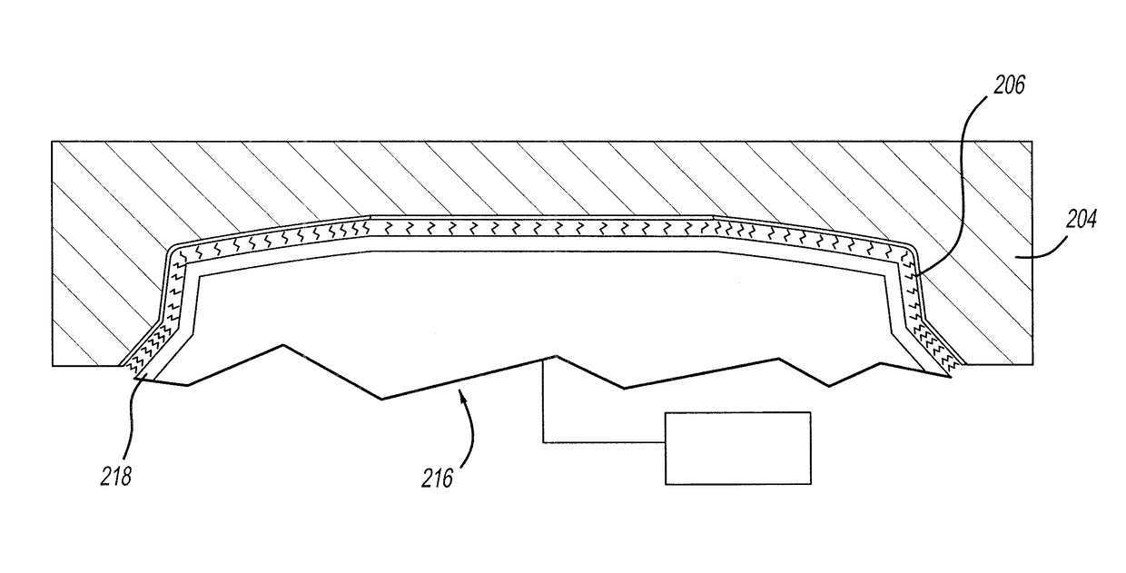
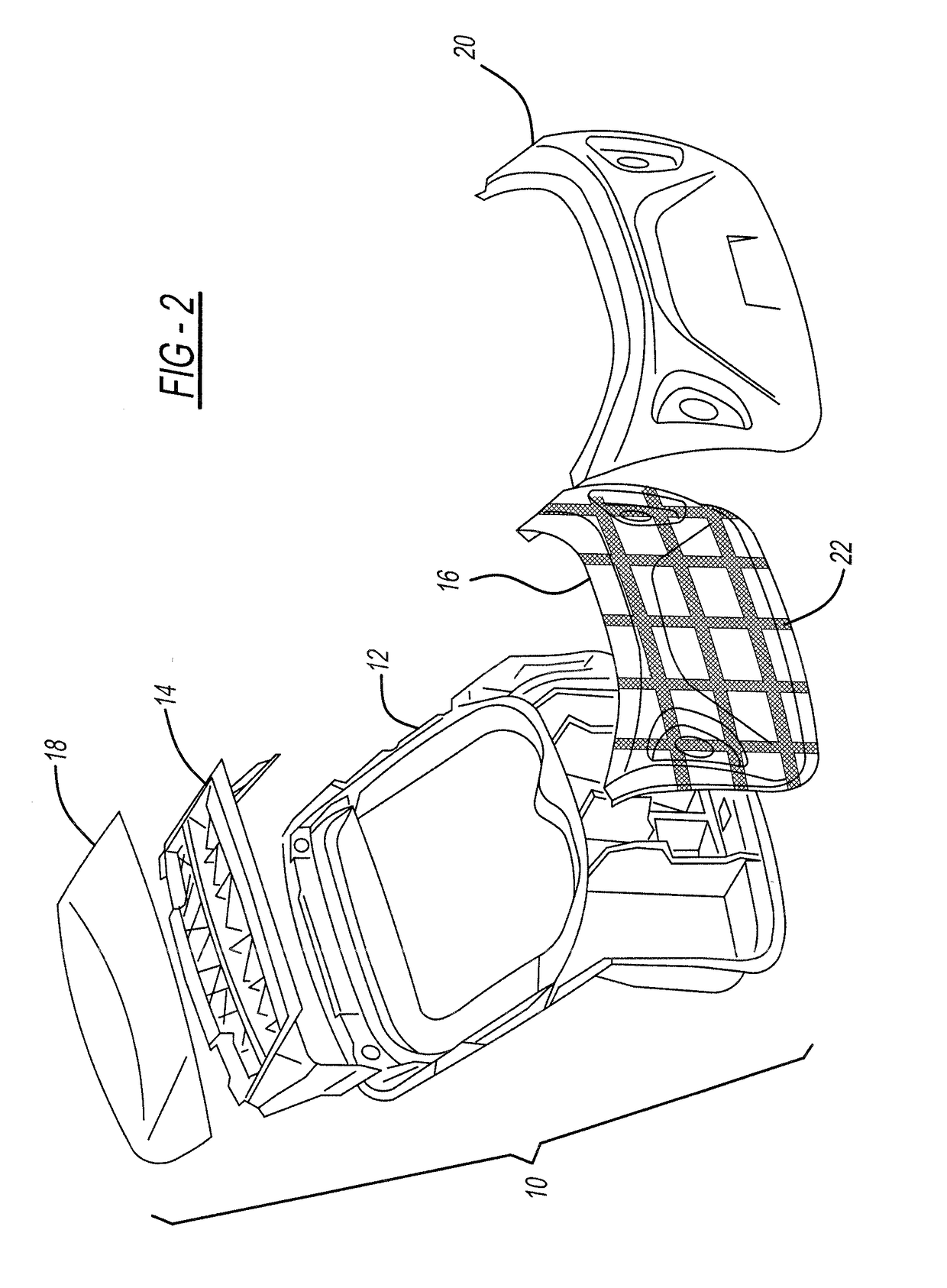
The present invention relates to a process for infrared welding exterior body panel assemblies, particularly liftgate assemblies, using an infrared welding tooling system. The process allows for more shapes, improved surface quality, a sealed weld, and the creation of a strong and efficient structure. The invention also provides joint designs for welding thermoplastic exterior body panels, which can eliminate or reduce problems associated with bonding systems. The joint design includes various construction methods such as surface to surface, ribs to surface, ribs to ribs, and combinations thereof. Overall, the process improves strength, appearance, and seals against gas fumes, water, and other materials, and reduces or eliminates material and processing steps.

Problems solved by technology

Such parts as liftgates for any vehicle are traditionally made from stamped steel panels that are heavy and have a high tooling cost.
Traditional steel liftgates are expensive investments, heavy, take up a lot of OEM floor space in areas from the stamping plant, body shop, paint shop, and trim line.
Further, steel liftgates have limited styling flexibility, take a lot of time to tool, and have corrosion concerns.
Steel and SMC liftgates have a mass penalty over thermoplastics.
There are also styling restrictions with traditional sheet metal components.
Thermoplastic polyolefin (TPO)—filled TPO (e.g., glass filled) or non-filled TPO—is another alternative material to steel and SMC but it is a difficult material to work with.
TPO has been used for some parts but is thought of as being difficult to use because it is too soft, sensitive, flexible or difficult to process for making larger parts.
The use of TPO has generally been limited to smaller parts.
TPO parts have also been generally limited to being welded first before painting Class A surfaces.
Welding before painting is inefficient because it adds processing steps, e.g., powerwashing, masking, etc.
Thermoplastic composite type materials used for liftgate applications also have difficulty meeting customer performance specifications.
One of the problems that has been encountered is that pieces of the composite liftgate, when experiencing a crash are projected into the interior compartment of the vehicle.
While this arrangement can work to pull together very large broken pieces of a liftgate at the time of collision, it does not prevent or stop larger pieces that shatter and form shards from being projected into the department at the time of the collision.
Bonding is more typical for joining panels of these assemblies, but bonding is time consuming, expensive, very sensative, weaker and takes a lot of manufacturing space.
Bonding, ultrasonic welding, or vibration welding of Class-A, painted thermoplastic automobile exterior parts are all particularly problematic and fail to provide required strength and surface appearance.
Known attempts to try to overcome the problems with bonding have utilized ultrasonic welding, vibration welding (bulbs or wires), and are utilized on some spoiler applications, but there are issues with Class-A read through, sink marks, strength or structure weakness, limited shape allowance, the weld not being continuous, and not sealed, etc.
The combination creates debris.

Method used


Image

  • Infrared welded exterior panel assembly and process of making same
  • Infrared welded exterior panel assembly and process of making same
  • Infrared welded exterior panel assembly and process of making same

Examples


Embodiment Construction

[0030]The following description of the preferred embodiment(s) is merely exemplary in nature and is in no way intended to limit the invention, its application, or uses.

[0031]Referring to the figures generally, there are several advantages obtained by the present invention. One aspect is that when one or more larger components, e.g., liftgate inner panels and outer panels, that is / are out of tolerance, e.g., warped, twisted, or otherwise out of specification or nested imperfectly, are infrared welded according to the present inventive process—the assembly is brought into tolerance. Another aspect of the present invention is that components made of sensitive materials (e.g., such as filled or non-filled thermoplastic polyolefin (TPO) parts, TPO parts with Class A surface(s), painted parts, molded-in color parts, TPO material with painted Class A surface(s), sensitive to read through, heat sensitive, etc) can be infrared welded with another component, e.g., a structural component, acco...


PUM

PropertyMeasurementUnit
temperatureaaaaaaaaaa
clamping timeaaaaaaaaaa
timeaaaaaaaaaa

Abstract

An exterior body panel assembly having a Class A painted surface, mold-in color or non-Class A surface, and process of infrared welding components of the assembly. Panels of the assembly are placed on a nesting structure and the inside half of the structures are brought together with the other for a fit check. Panels are separated and an infrared heating fixture then heats the various areas to be heated on the panels. The areas on the panels are heated depending on the thicknesses of the parts at each area and surface geometries to be welded. The parts are immediately clamped back together under pressure for joining and cooling of the joined surfaces in the clamped arrangement.

Description

FIELD OF THE INVENTION[0001]The present invention relates to exterior body panel assemblies for automobiles. More specifically, to a composite liftgate and method of manufacture.BACKGROUND OF THE INVENTION[0002]One of the current trends in the automobile industry is to lower vehicle weight to help achieve better fuel economy, thus helping to meet fuel economy standards and to offset the higher fuel prices. Lighter weight components are also attempted for easier manipulation by a user when desired. Another trend is that there is a broader range of vehicle models, which in turn reduces the volume of vehicles produced on a per model basis. Sport utility and crossover vehicles remain popular, and these typically include fairly heavy exterior body panels, such as rear liftgates, making these parts of the vehicle a target area for weight reduction. Such parts as liftgates for any vehicle are traditionally made from stamped steel panels that are heavy and have a high tooling cost. Traditio...

Claims


Application Information

Patent Timeline
Patent Type & Authority Patents(United States)
IPC IPC(8): B29C65/14B29C65/00B62D29/04B62D33/077B29C65/78
CPCB29C65/1412B29C65/7802B29C66/8141B62D33/077B29C66/81815B62D29/048B29C66/81261B62D25/00B62D33/023B62D25/105B62D29/043B62D35/007B62D65/06B29K2509/08B29C65/1416B29C65/1432B29C65/1467B29C66/112B29C66/1122B29C66/114B29C66/301B29C66/3474B29C66/3494B29C66/54B29C66/71B29C66/7212B29C66/7392B29C66/73921B29C66/7394B29C66/91413B29C66/919B29C66/929B29C66/949B29L2031/3055B29L2031/3044B60J5/107B29C66/545B29C66/532B29L2031/3014B29K2023/12B29K2309/08B29K2023/00B29C65/1419
Inventor CHAAYA, RIADBIRKA, MARK P.HARNEY, WILLIAM J. J.SALZMANN, HEINERKUNTZE, CHRISTOPHER J.HUOTARI, KEIJO J.
Owner MAGNA EXTERIORS INC
Learn More