
Tubular threaded joint having improved high-torque makeup properties

a technology of makeup and threaded joints, which is applied in the direction of screw threaded joints, couplings, pipe couplings, etc., can solve the problems of affecting the operation environment and operating efficiency, affecting the operation environment and human health, and raising the concern of adverse effects on the environment and humans, etc., to achieve high hardness, high wear resistance, and high resistance to sliding

Active Publication Date: 2018-07-03
VALLOUREC OIL & GAS FRANCE SAS +1
View PDF16 Cites 2 Cited by
  • Summary
  • Abstract
  • Description
  • Claims
  • Application Information

AI Technical Summary

Benefits of technology

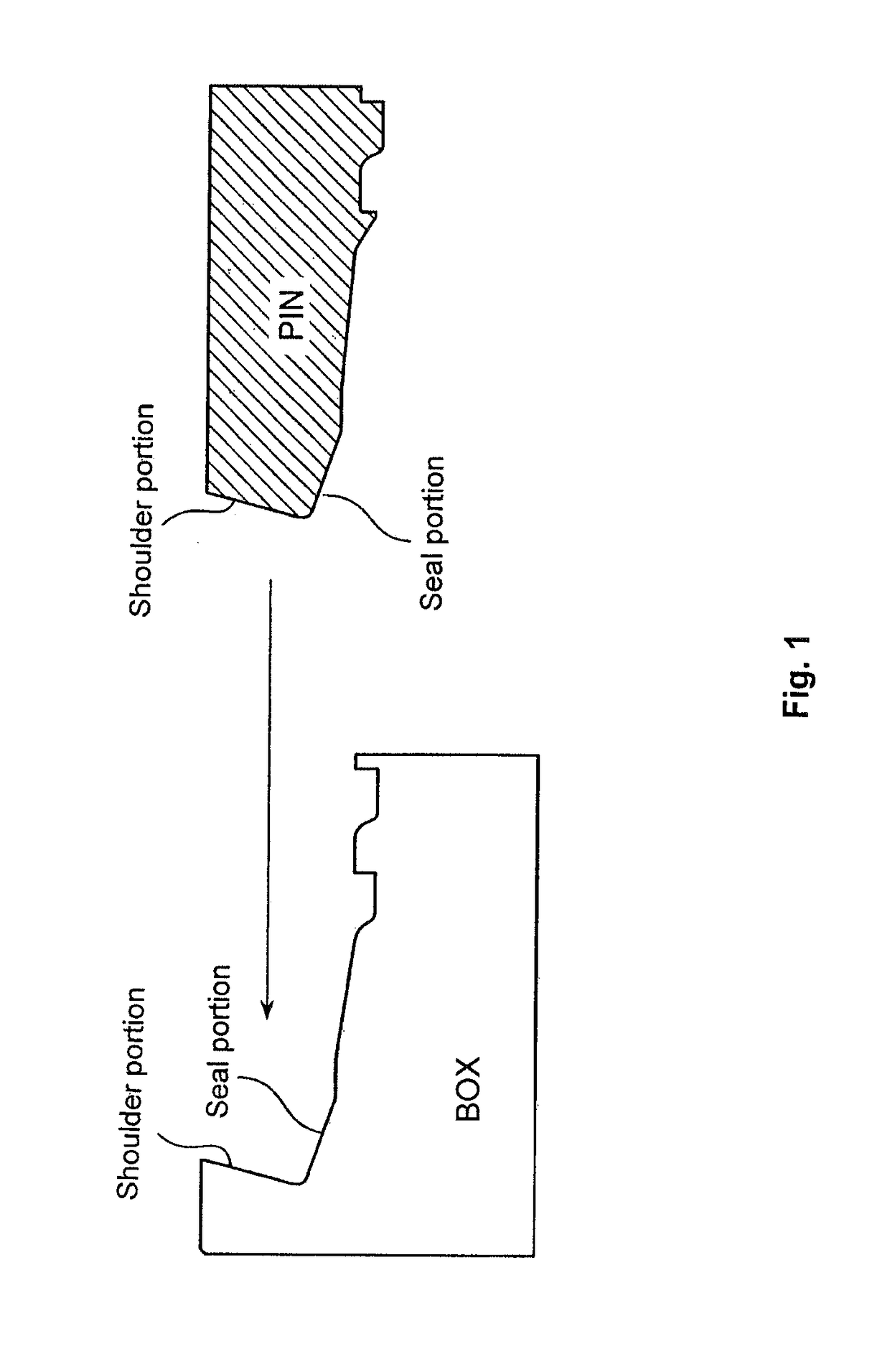
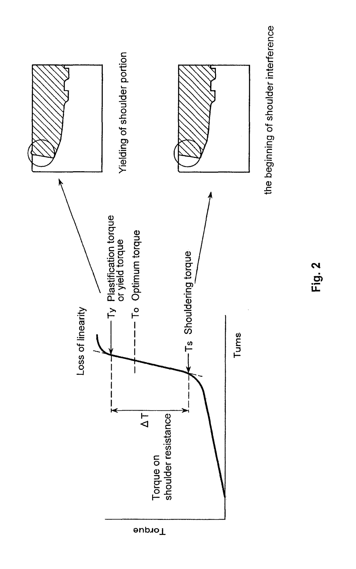
The present invention provides a tubular threaded joint with excellent galling resistance, gas tightness, and rust preventing properties. The joint has a special threaded joint design with seal portions and shoulder portions that guarantees gas tightness when made up with a high torque. The joint also has a lubricating coating that does not contain harmful heavy metals and a surface treatment coating that has a large ΔT, making it possible to carry out makeup operations without the occurrence of yielding of the shoulder portions or galling. The joint suppresses the occurrence of rust and continues to exhibit lubricating performance even after repeated makeup and breakout.

Problems solved by technology

However, as described below, the use of compound grease raises the concern of an adverse effect on the environment and humans.
At the time of makeup of a threaded joint, the applied grease is washed off or squeezed out to the exterior surface, and there is the possibility of an adverse effect on the environment and especially on sea life particularly due to harmful heavy metals such as lead.
In addition, the process of applying compound grease worsens the operating environment and operating efficiency and may cause harm to humans.
However, it is very difficult to form the low-friction lubricating layer on only the thread crests, roots, and stab flanks of the threaded portion without forming it on the thread load flanks

Method used


Image

  • Tubular threaded joint having improved high-torque makeup properties
  • Tubular threaded joint having improved high-torque makeup properties
  • Tubular threaded joint having improved high-torque makeup properties

Examples


example 1

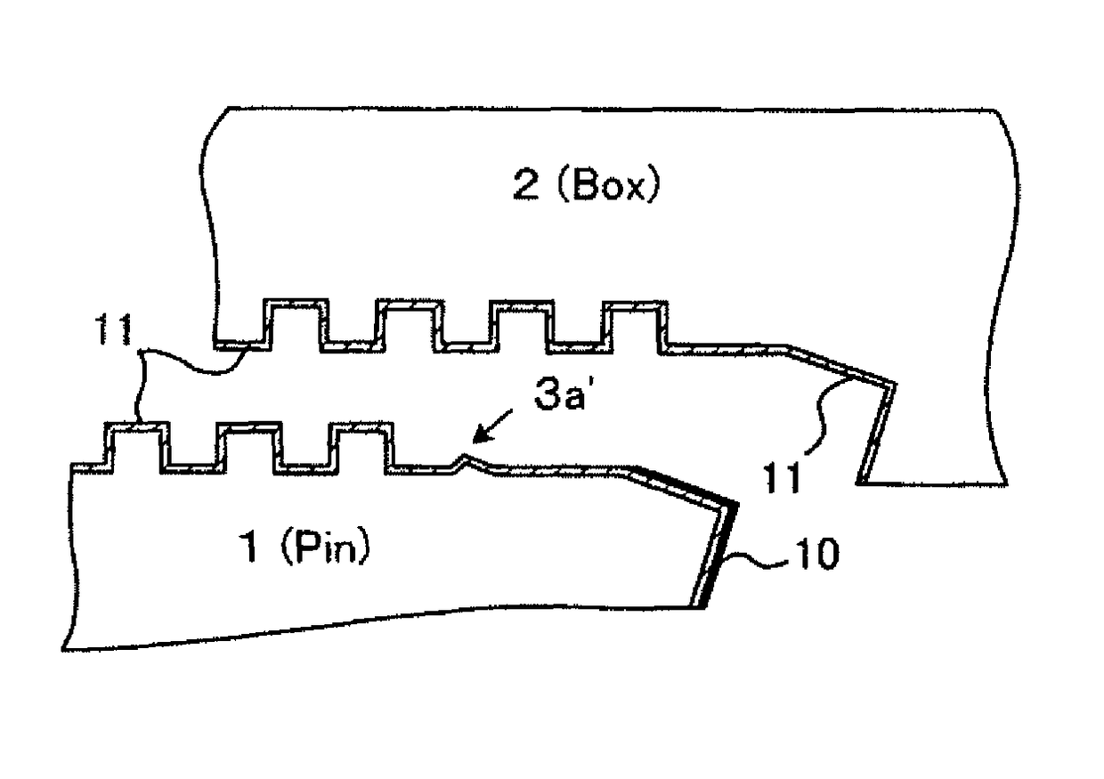
[0138]The following preparatory surface treatment and coating formation were carried out on the pin surface and the box surface of a special threaded joint made of carbon steel having the composition shown in Table 1 to form coatings having the structure shown in FIG. 5.

[0139][Box Surface]

[0140]The box surface was finished by machine grinding (surface roughness of 3 μm), and it was then subjected to Ni strike plating followed by Cu—Sn—Zn alloy plating (Cu: 56%, Sn: 36%, a remainder of Zn, the same applies below) both performed by electroplating to obtain plated coatings having an overall thickness of 5 μm. The surface roughness after this preparatory surface treatment was 2 μm.

[0141]On the box surface which had undergone the preparatory surface treatment, solid lubricating coating 1 shown in Table 3 (a coating of a polyetherether ketone (PEEK) resin containing PTFE added as lubricating particles, Knoop hardness Hk of 80, coating thickness of approximately 20 μm) was formed on the un...

example 2

[0147]The below-described preparatory surface treatment and coating formation were carried out on the pin surface and the box surface of a special threaded joint made of carbon steel having the composition shown in Table 1 to form coatings having the structure shown in FIG. 6(A).

[0148][Box Surface]

[0149]The box surface was finished by machine grinding (surface roughness of 3 μm), and it was subjected to preparatory surface treatment by immersion for 20 minutes in a manganese phosphating solution at 90-95° C. to form a manganese phosphate coating (surface roughness of 14 μm) having a thickness of 18 μm.

[0150]On the entirety of the box surface which had undergone this preparatory surface treatment, solid lubricating coating 3 (fluoroplastic with a Knoop hardness Hk of 35 and a coating thickness of approximately 20 μm) was formed.

[0151][Pin Surface]

[0152]The pin surface underwent exactly the same preparatory surface treatment and coating formation as the pin surface of Example 1. The K...

example 3

[0154]The below-described preparatory surface treatment and coating formation were carried on the pin surface and the box surface of a special threaded joint made of carbon steel having the composition shown in Table 1 to form coatings having the structure shown in FIG. 6(B).

[0155][Box Surface]

[0156]Preparatory surface treatment of the box surface was carried out in the same manner as for the box surface in Example 1 (grinding and then Ni strike plating followed by Cu—Sn—Zn alloy plating). On the box surface which had undergone the preparatory surface treatment, solid lubricating coating 2 shown in Table 3 (a coating of a polyamide-imide (PAI) resin and a fluoroplastic containing PTFE and MoS2 as lubricating particles, Knoop hardness Hk of 62, coating thickness of approximately 22 μm) was first formed on the unthreaded metal contact portion, and then solid lubricating coating 4 in Table 3 (a coating of an epoxy resin containing graphite as lubricating particles, Knoop hardness Hk of...


PUM

PropertyMeasurementUnit
thicknessaaaaaaaaaa
thicknessaaaaaaaaaa
depthaaaaaaaaaa

Abstract

A tubular threaded joint has a pin and a box. Each having a contact surface comprising a threaded portion and an unthreaded metal contact portion including a seal portion and a shoulder portion. A solid lubricating coating having a relatively high Knoop hardness is formed on a portion including the shoulder portion of the contact surface, such as the unthreaded metal contact portion including the shoulder portion and the seal portion, of at least one of the pin and the box. A solid lubricating coating having a relatively low Knoop hardness is formed at least on the remaining portion of the contact surface, such as the threaded portion. The threaded joint has excellent galling resistance, gas tightness, and rust preventing properties. The joint does not readily undergo yielding of shoulder portions even when made up with a high torque, thereby making it possible to perform makeup in a stable manner.

Description

TECHNICAL FIELD[0001]This invention relates to a tubular threaded joint for use in connecting steel pipes and particularly oil country tubular goods. A tubular threaded joint according to the present invention can reliably exhibit excellent galling resistance without application of a lubricating grease such as compound grease, which has in the past been applied to threaded joints at the time of makeup of oil country tubular goods. As a result, a tubular threaded joint according to the present invention can avoid the adverse effects of compound grease on the global environment and humans. In addition, the joint does not readily undergo yielding even when it is made up with a high torque, so a stable metal-to-metal seal can be realized with an adequate margin.BACKGROUND ART[0002]Oil country tubular goods such as tubing and casing used for digging of oil wells for crude oil or gas oil are typically connected to each other using tubular threaded joints. In the past, the depth of oil wel...

Claims


Application Information

Patent Timeline
Patent Type & Authority Patents(United States)
IPC IPC(8): F16L15/00C10M171/00F16L58/18C10M177/00E21B17/042
CPCF16L15/00C10M177/00E21B17/042F16L58/182C10M171/00F16L2201/40C10M2201/0663C10M2209/1003C10M2213/0623C10M2217/0443C10N2230/00C10N2230/06C10N2230/12C10N2240/22C10N2250/14C10N2280/00F16L57/06C10N2030/12C10N2030/06C10N2040/34C10N2050/023C10N2080/00C10N2030/00Y02E10/10
Inventor GOTO, KUNIO
Owner VALLOUREC OIL & GAS FRANCE SAS
Learn More