
Floating resistance of I/O circuit on integrated circuit chip

An integrated circuit and resistor technology, which is applied in the field of multiple I/O circuit floating resistors, can solve problems such as increasing product costs, and achieve the effects of improved consistency, good stability, and improved resistance accuracy

Inactive Publication Date: 2007-07-04
徐平
View PDF0 Cites 0 Cited by
  • Summary
  • Abstract
  • Description
  • Claims
  • Application Information

AI Technical Summary

Problems solved by technology

And because the number of I / O circuits on the same integrated circuit chip is relatively large, if the same integrated circuit chip of each I / O circuit impedance variety is designed and manufactured separately, the cost of the product will be increased.

Method used


Image

  • Floating resistance of I/O circuit on integrated circuit chip
  • Floating resistance of I/O circuit on integrated circuit chip
  • Floating resistance of I/O circuit on integrated circuit chip

Examples


Embodiment 1

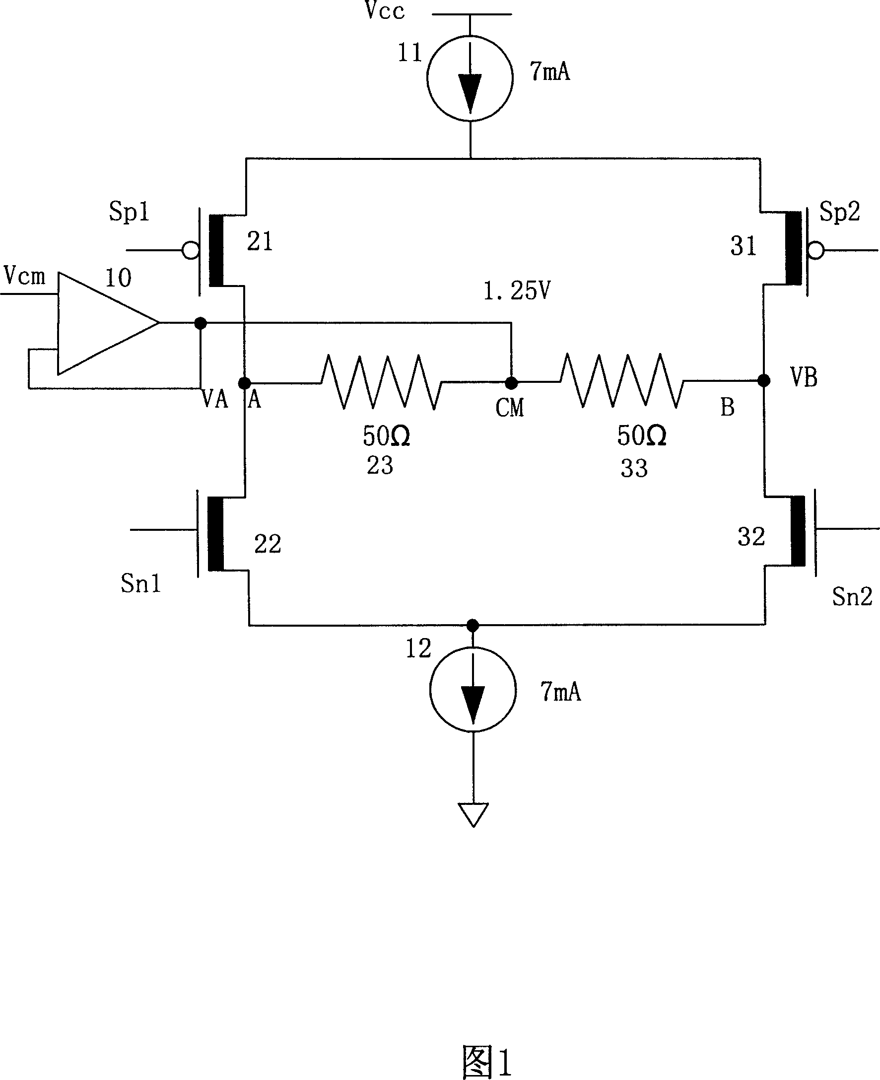
[0017] The electrical structure of a dual low voltage differential signal I / O on a 17-way dual low voltage differential signal (LVDS) I / O integrated circuit chip is shown in FIG. 1 . A P-type field effect transistor 21 and an N-type field effect transistor 22 of the first group of low-voltage differential signal I / O are connected in series between the constant current source 11 connected to the power supply voltage Vcc and the constant current source 12 connected to the ground level , the gate Sp1 of the P-type field effect transistor 21 and the gate Sn1 of the N-type field effect transistor 22 are two input terminals of the first group of low-voltage differential signals. The signal output point A of the first group of low-voltage differential signal I / O, that is, the connection point of the P-type field effect transistor 21 and the N-type field effect transistor 22 is connected with a floating resistor 23 . The other end of the floating resistor 23 is connected to the CM poi...


PUM


Abstract

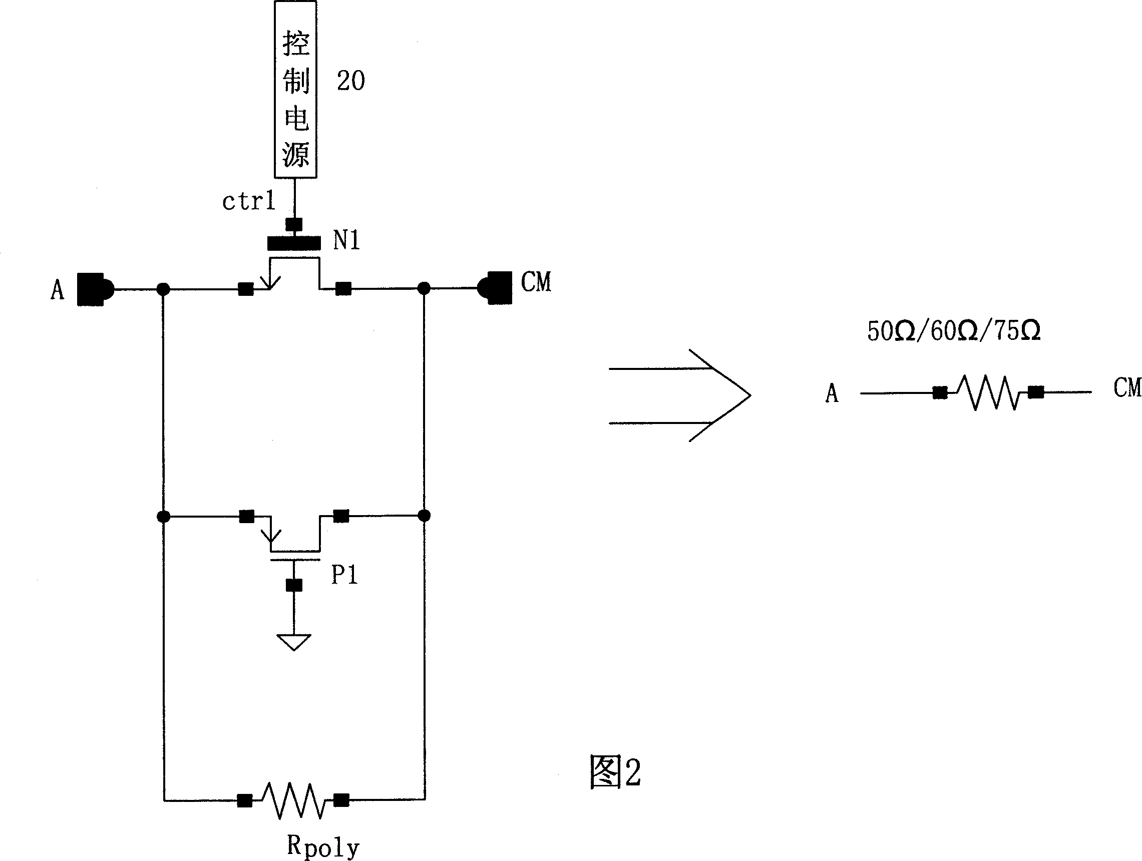
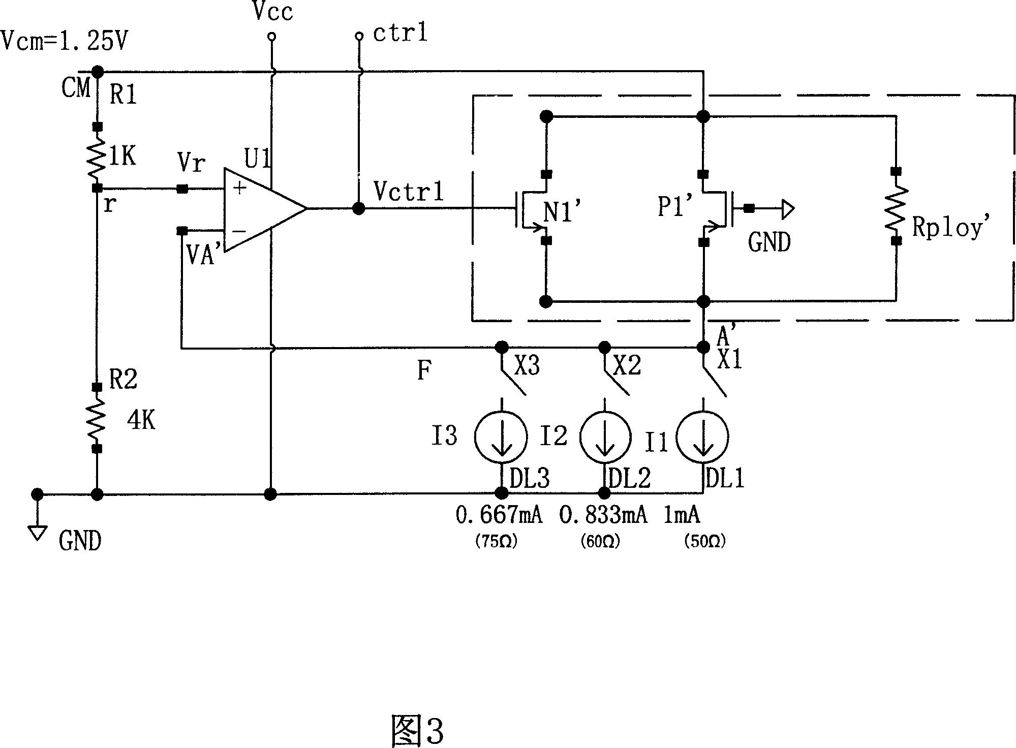
The invention is the I / O circuit floating resistance of the IC chip, which relates to multiple I / O circuit floating resistances integrated in IC chip using CMOS technology. Every floating resistance of the invention has a polysilicon resistance; the both end of polysilicon resistance parallels a P-type FET and an N-type FET, in which the constant-voltage end of the polysilicon resistor links the drain of the said two FETs, and the fluctuant-voltage end of the polysilicon resistance links the source of the two FETs; the gate of P-type FET connecting the ground, the gate of N-type FET connecting the voltage output of the constant-voltage controlled power supply. It solves the low precision of the polysilicon floating resistance, and the problem that need to separately design and manufacture, and the high cost of products, when there are several different I / O circuit impedances in the same IC chip. In the invention, the parasitic capacitance of floating resistance is small, which suitable for work in high-speed I / O.

Description

technical field [0001] The invention relates to a resistor on an integrated circuit chip, in particular to a floating resistor of a plurality of I / O circuits integrated on the integrated circuit chip by using CMOS technology to achieve more accurate impedance matching. technical background [0002] The floating resistance of the I / O circuit on the integrated circuit chip manufactured by the CMOS process generally adopts polysilicon (poly) resistance, and the resistance value of this resistance is designed according to the length, and the accuracy can only reach ± ​​20%. Since the resistance value of the floating resistance of the I / O circuit on the integrated circuit chip directly affects the external impedance of the I / O circuit, the precision of the resistance value of the floating resistance for impedance matching in the I / O circuit on various high-speed integrated circuit chips is required to reach ±5%-10%, so the floating resistance of polysilicon is not suitable for us...

Claims


Application Information

Patent Timeline
Patent Type & Authority Applications(China)
IPC IPC(8): H01L27/02H01L23/64
CPCH01L2924/0002
Inventor 徐平
Owner 徐平
Learn More