
Uv-ray irradiator

An irradiation device, ultraviolet technology, applied in lighting devices, lighting and heating equipment, semiconductor devices of light-emitting elements, etc., can solve the problems of short life maintenance work, long warm-up time, environmental problems, etc., achieve reliable performance, reduce consumption The effect of electricity and life guarantee

Inactive Publication Date: 2007-06-27
LINTEC CORP
View PDF1 Cites 3 Cited by
  • Summary
  • Abstract
  • Description
  • Claims
  • Application Information

AI Technical Summary

Problems solved by technology

As a result, the device has disadvantages of large size and high power consumption
In addition, in addition to frequent maintenance work due to the short life of the lamp, it is necessary to keep the lamp on during operating hours due to the long so-called warm-up time in order to meet the ultraviolet irradiation conditions, resulting in a large amount of power consumption
In addition, effective irradiation control cannot be performed for a flat area to be irradiated, so electric energy waste is unavoidable, and because the lamp uses mercury, it will cause environmental problems during waste disposal.

Method used


Image

  • Uv-ray irradiator
  • Uv-ray irradiator
  • Uv-ray irradiator

Examples


Embodiment Construction

[0028] Hereinafter, embodiments of the present invention will be described with reference to the drawings.

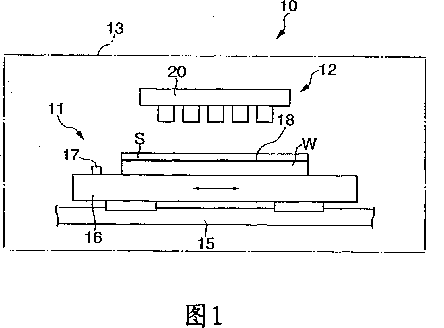
[0029] FIG. 1 is a schematic front view of an embodiment of the present invention in which an ultraviolet irradiation device of the present invention is used in a wafer processing device. In this figure, the ultraviolet irradiation device 10 has a wafer support section 11 that absorbs and supports a wafer as an object to be irradiated; an ultraviolet irradiation section 12 disposed on the wafer support section 11 substantially parallel to the wafer W; And the processing chamber 13 of the ultraviolet irradiation part 12.

[0030] The wafer support portion 11 includes a guide rod 11 extending in the left-right direction in FIG. 1; a table 16 that can move along the guide rod 15 and whose planar shape is approximately square; Multiple illuminance sensors 17 arranged in different directions. The upper surface of the stage 16 is a suction surface, and the position of the w...


PUM


Abstract

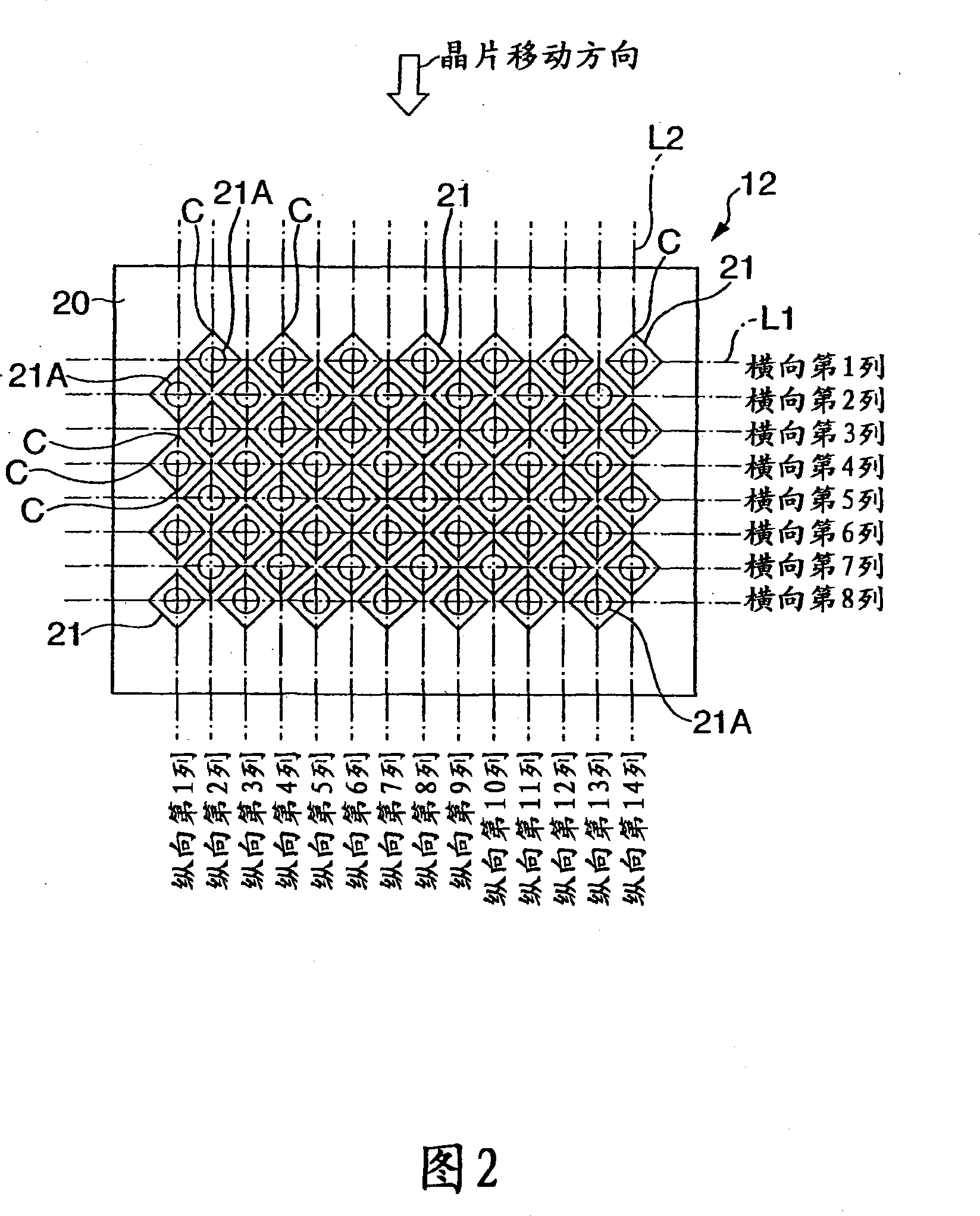
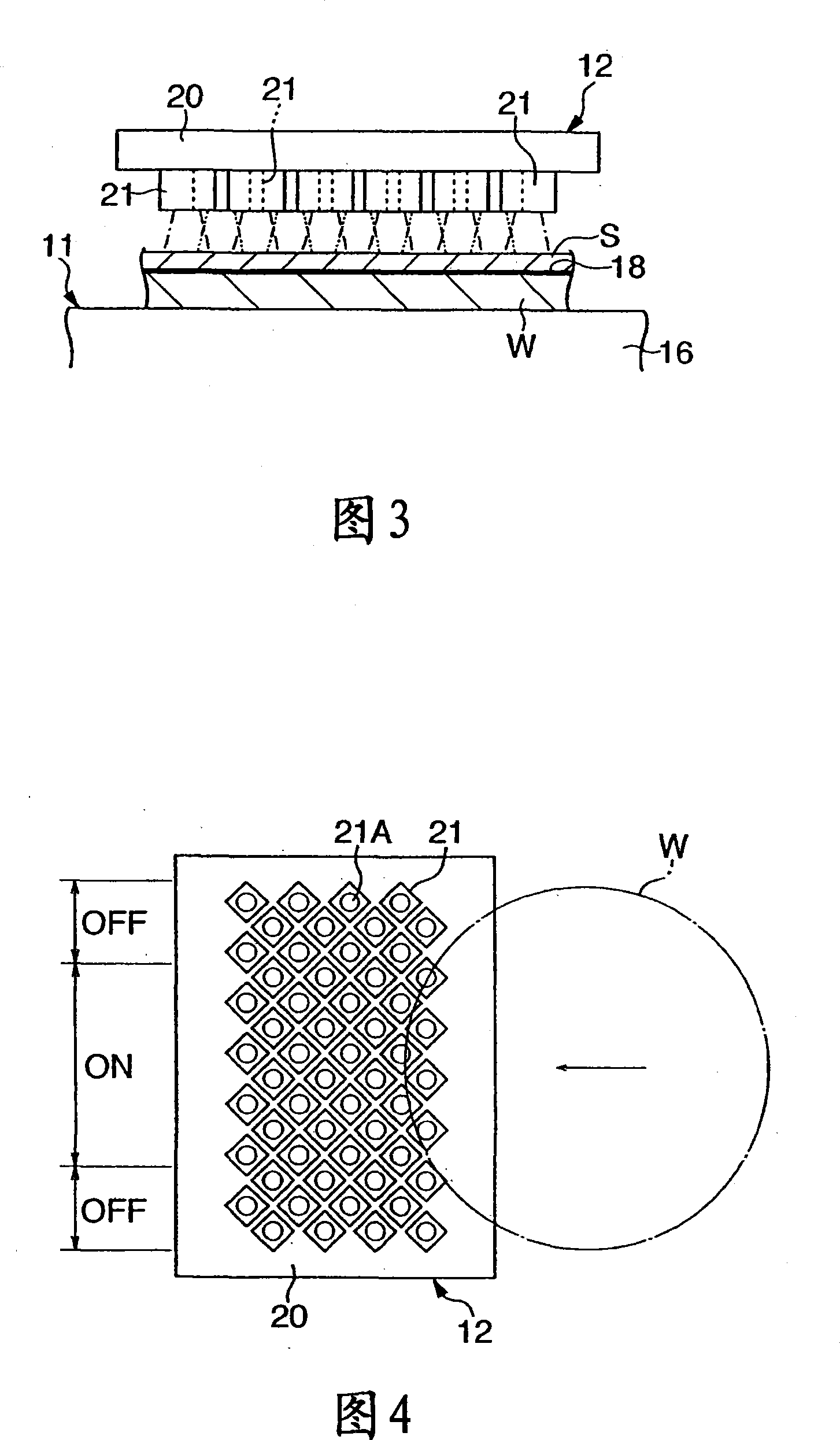
A UV-ray irradiator comprising a UV-ray irradiating section (12) having a plurality of UV-ray emitting diodes (21) arranged on a substrate (20) and disposed oppositely to a body being irradiated, i.e. a semiconductor wafer, applied with a protective sheet S through a UV-curing adhesive layer. The UV-ray emitting diodes (21) are arranged, at a constant interval, on a plurality of lines L1 substantially perpendicularly intersecting the direction of relative movement with respect to the wafer such that a part of the UV-ray emitting diodes (21) in the adjacent row is located between the adjacent UV-ray emitting diodes (21) in each row.

Description

technical field [0001] The invention relates to an ultraviolet irradiation device, in particular to an ultraviolet irradiation device using light-emitting diodes. Background technique [0002] In an apparatus for processing a semiconductor wafer (hereinafter referred to simply as a wafer), for example, a predetermined process is performed with a protective tape attached to the circuit surface of the wafer. The adhesive surface of this protective tape is made of ultraviolet curable resin, and its adhesive force will be weakened by treating the ultraviolet curable resin with an ultraviolet irradiation device, so that the protective tape is easy to peel off. [0003] As an ultraviolet irradiation device, there is known a device arranged in such a manner that, for example, a lamp box is placed at a position facing the surface of the wafer, and a high-pressure mercury lamp, or a metal halide lamp, etc. are placed in the lamp box (refer to Patent Document 1) [0004] Patent Docum...

Claims


Application Information

Patent Timeline
Patent Type & Authority Applications(China)
IPC IPC(8): H01L21/68H01L33/00H01L23/50
CPCH01L2224/10F21K9/00H01L21/67115H01L21/324
Inventor 河崎仁彦小林贤治
Owner LINTEC CORP
Learn More