
Multiple mask exposure system and method

An exposure system and photomask technology, applied in the field of exposure systems, can solve problems such as inability to improve production efficiency and poor alignment accuracy, and achieve the effects of eliminating alignment problems, improving productivity, and reducing manufacturing costs

Active Publication Date: 2007-06-27
TAIWAN SEMICON MFG CO LTD
View PDF0 Cites 3 Cited by
  • Summary
  • Abstract
  • Description
  • Claims
  • Application Information

AI Technical Summary

Problems solved by technology

[0005] The main purpose of the present invention is to overcome the defects existing in the existing exposure system, and provide a multi-mask exposure system with a new structure, which is used to improve the traditional multi-mask needs to go through multiple exposure processes, and the production efficiency cannot be improved. making it more practical
[0006] Another object of the present invention is to overcome the defects of the existing exposure system and provide a multi-mask exposure system to improve the traditional multi-mask exposure process and need to replace several masks. The problem of poor accuracy, so it is more suitable for practical

Method used


Image

  • Multiple mask exposure system and method
  • Multiple mask exposure system and method
  • Multiple mask exposure system and method

Examples


Embodiment Construction

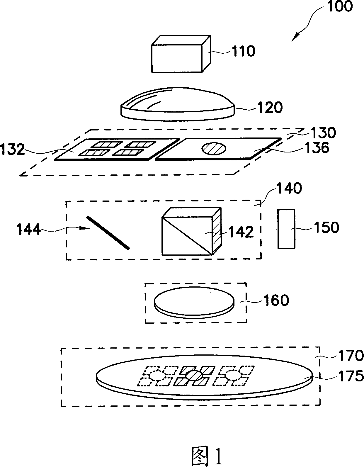
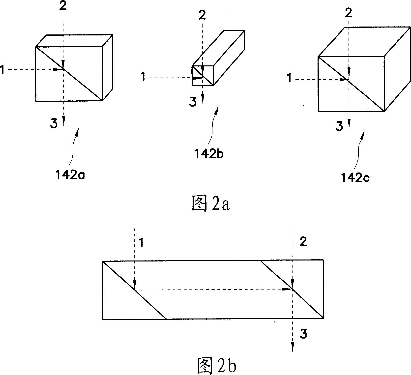
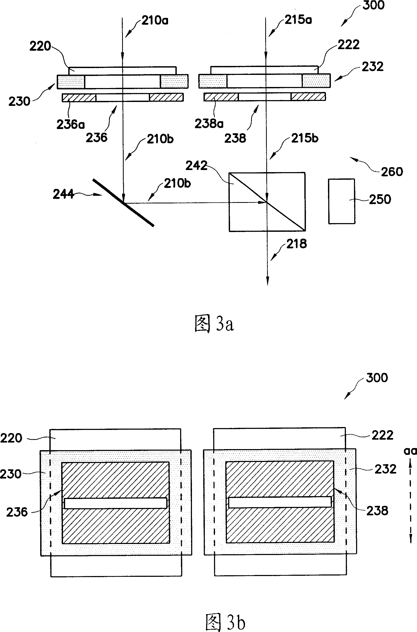
[0067] In order to further explain the technical means and effects of the present invention to achieve the intended purpose of the invention, the specific implementation and structure of the multiple mask exposure system and its exposure method according to the present invention will be described below in conjunction with the accompanying drawings and preferred embodiments. , method, step, feature and effect thereof, detailed description is as follows.

[0068] The present invention relates to a multiple exposure system, and in particular to a multiple exposure system capable of stacking multiple photomasks. The content disclosed below provides many different embodiments and illustrations to disclose the scope of the present invention. various features. The specific embodiments of the compositions and arrangements described below are intended to clearly express the technical features and achieved technical means of the present invention, which are merely examples, rather than ...


PUM

PropertyMeasurementUnit
wavelengthaaaaaaaaaa

Abstract

An exposure system includes a mask stage module adapted for holding a first mask and a second mask, wherein the first mask is configured for illumination by a first beam to form a transformed first beam having a first pattern from the first mask and the second mask is configured for illumination by a second beam to form a transformed second beam having a second pattern from the second mask. The exposure system also includes a beam combiner configured to combine the transformed first and second beams to form a resultant beam, wherein the resultant beam is projected into a substrate coated with a photoresist layer.

Description

technical field [0001] The invention relates to an exposure system, in particular to an exposure system capable of stacking multiple photomasks and an exposure method thereof. Background technique [0002] In semiconductor integrated circuit (IC) technology, the development of minimizing feature size and maximizing packing density is very rapid. Feature size minimization is the creation of smaller feature structures through the improvement and enhancement of lithography technology. For example, an alternating phase shifting mask can project smaller features with a preset imaging tool. The alternating phase shift mask often requires the addition of a second correction mask, however, double exposure and mask replacement often results in higher manufacturing costs, lower productivity and more alignment problems. [0003] It can be seen that the above-mentioned existing lithography system obviously still has inconveniences and defects in product structure, manufacturing method...

Claims


Application Information

Patent Timeline
Patent Type & Authority Applications(China)
IPC IPC(8): G03F7/20H01L21/027
Inventor 林本坚
Owner TAIWAN SEMICON MFG CO LTD
Learn More