Heat exchanger

A technology for heat exchangers and heat exchange tubes, applied in the direction of indirect heat exchangers, heat exchanger types, heat exchanger shells, etc., can solve problems such as the need to improve the effect of condensed water, and achieve improved drainage efficiency, high drainage efficiency, Effect of preventing aggregation and freezing

Inactive Publication Date: 2007-06-13
KEIHIN THERMAL TECH CORP
View PDF2 Cites 6 Cited by
  • Summary
  • Abstract
  • Description
  • Claims
  • Application Information

AI Technical Summary

Problems solved by technology

[0010] However, the effect of the evaporator disclosed in the latter publication to discharge the condensed water on the top surface of the lower case still needs to be improved.

Method used


Image

  • Heat exchanger
  • Heat exchanger
  • Heat exchanger

Examples


Embodiment Construction

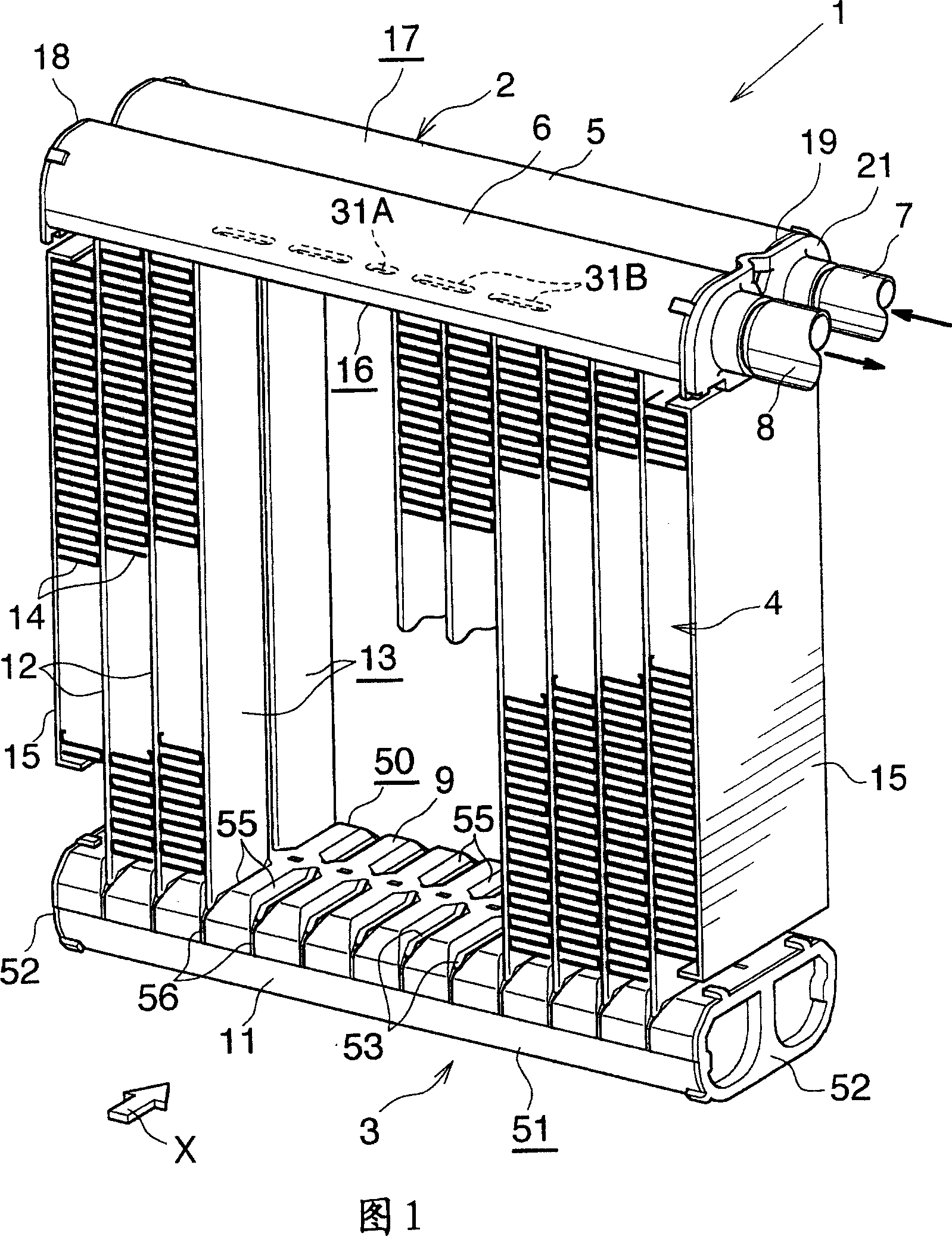
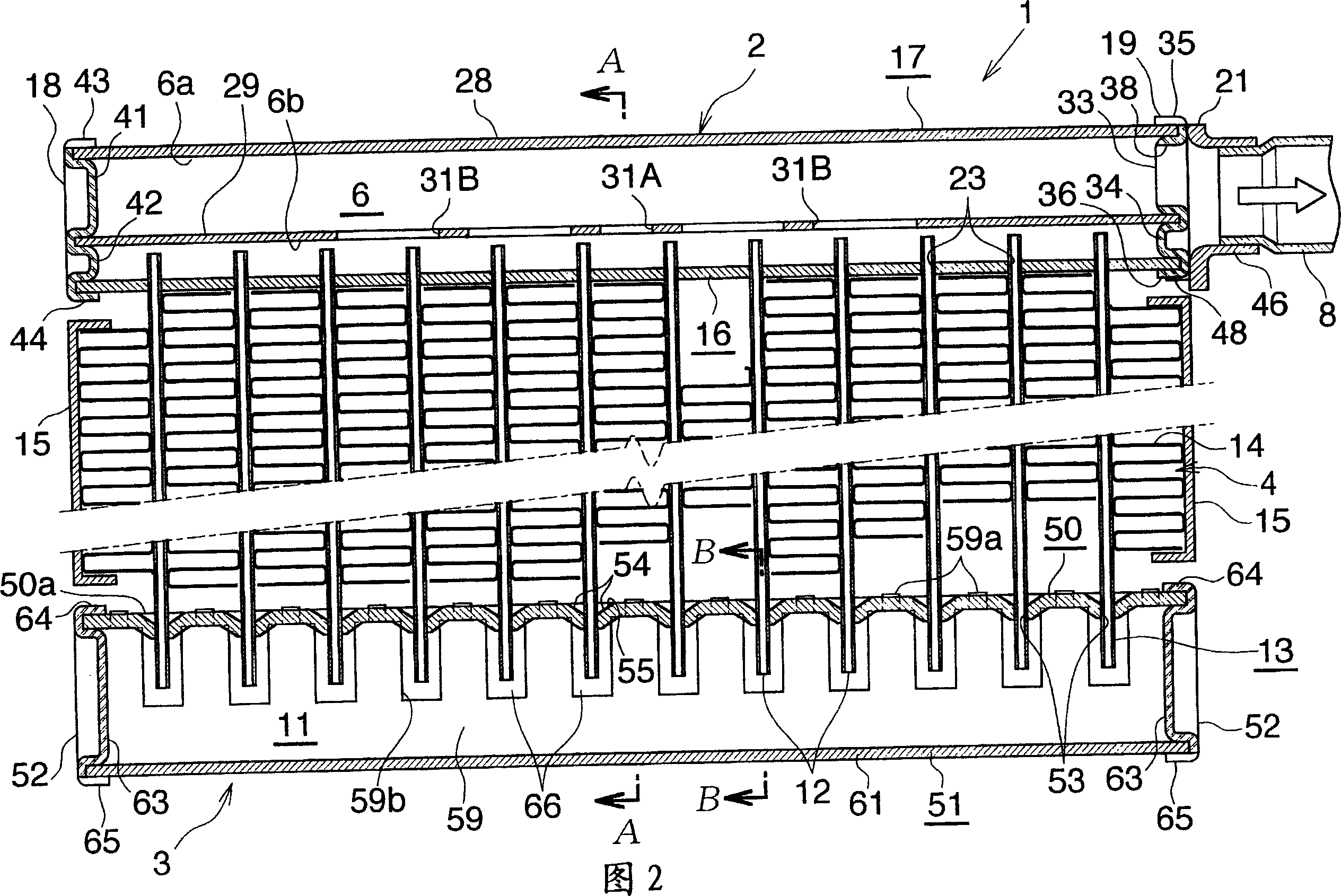
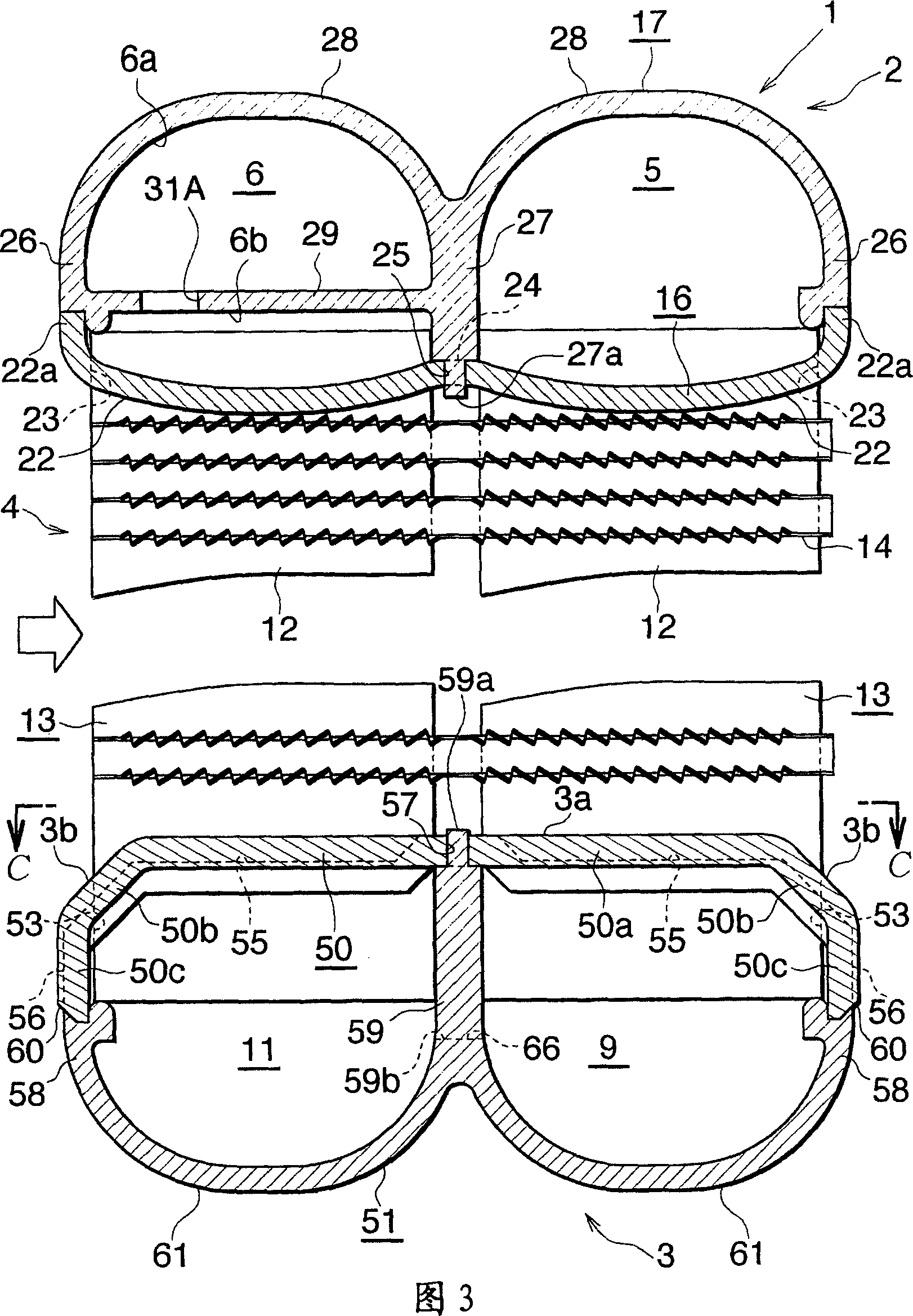
[0057] Embodiments of the present invention will be described below with reference to the drawings. This embodiment is a heat exchanger of the present invention, which is used as an evaporator in a motor vehicle air-conditioning unit in which a chlorofluorocarbon refrigerant is used.

[0058] Fig. 1 and 2 show the overall structure of the evaporator of the motor vehicle air conditioner that adopts heat exchanger of the present invention,

[0059] Figures 3 to 8 show the structure of the main components, and Figure 9 shows how the refrigerant flows through the evaporator.

[0060] 1 and 2 show an evaporator 1 for a motor vehicle air conditioner in which a chlorofluorocarbon refrigerant is used. The evaporator 1 includes an aluminum refrigerant inlet-outlet box 2 and an aluminum refrigerant diversion box 3 (lower box) arranged to be vertically separated, and a switch arranged between the two boxes 2, 3. Thermal core piece 4.

[0061] The refrigerant inlet-outlet box 2 include...


PUM


Abstract

A heat exchanger for use as an evaporator 1 comprises a heat exchange core having a plurality of heat exchange tubes 12 arranged in a left-right direction at a spacing, and a refrigerant turn tank 3 as a lower tank disposed toward a lower end of the heat exchange core. The heat exchange tubes 12 are inserted through respective tube insertion holes 53 formed in the turn tank 3 and joined to the tank 3. The turn tank 3 has drain grooves 56 each extending from a forwardly or rearwardly outer end of each of the tube insertion holes 53 for discharging condensation water to below the turn tank 3 therethrough. Each of the drain grooves 56 has a bottom extending gradually downward as the bottom extends away from the tube insertion hole 53. When the exchanger is used as the evaporator 1, the top surface of the turn tank 3 can be drained of water with an improved efficiency.

Description

[0001] Cross References to Related Applications [0002] This application is filed pursuant to 35 U.S.C. §111(a) and is required by 35 U.S.C. §119(e)(1) to be filed under 35 U.S.C. §111(b) on July 8, 2004 and provisional on June 8, 2005 Filing date benefits for applications No. 60 / 585,835 and No. 60 / 688,353. technical field [0003] The invention relates to a heat exchanger suitable for use as, for example, an evaporator of a motor vehicle air-conditioning system having a refrigeration circuit for a motor vehicle. [0004] The downstream side of the air flow (the direction indicated by the arrow X in Fig. 1, the right-hand side of Fig. 3) of the air passing through the gap between the adjacent pairs of heat exchange tubes of the heat exchanger is described herein and in the appended claims is referred to as the "front", while the opposite side is referred to as the "rear". In addition, the upper, lower, left and right sides of the heat exchanger viewed from the rear to the f...

Claims


Application Information

Patent Timeline
Patent Type & Authority Applications(China)
IPC IPC(8): F28F9/02F25B39/02B60H1/32
CPCB60H1/00328F25B39/02F25B2309/061F28D1/05391F28F9/0224F28F9/0278F28F17/005F28F2220/00F28F2265/06
Inventor 东山直久渡边纯孝山内忍
Owner KEIHIN THERMAL TECH CORP
Why Eureka
Try Eureka