Accumulator cell internal resistance and degradation state on-line monitoring method and system
A technology of deterioration state and monitoring system, applied in the direction of measuring resistance/reactance/impedance, measuring electricity, measuring devices, etc., can solve the problems of reduced amplitude of effective current change, increased battery test, and damage to the integrity of backup energy, etc., to achieve Accurately Measured Effects
- Summary
- Abstract
- Description
- Claims
- Application Information
AI Technical Summary
Problems solved by technology
Method used
Image
Examples
Embodiment 1
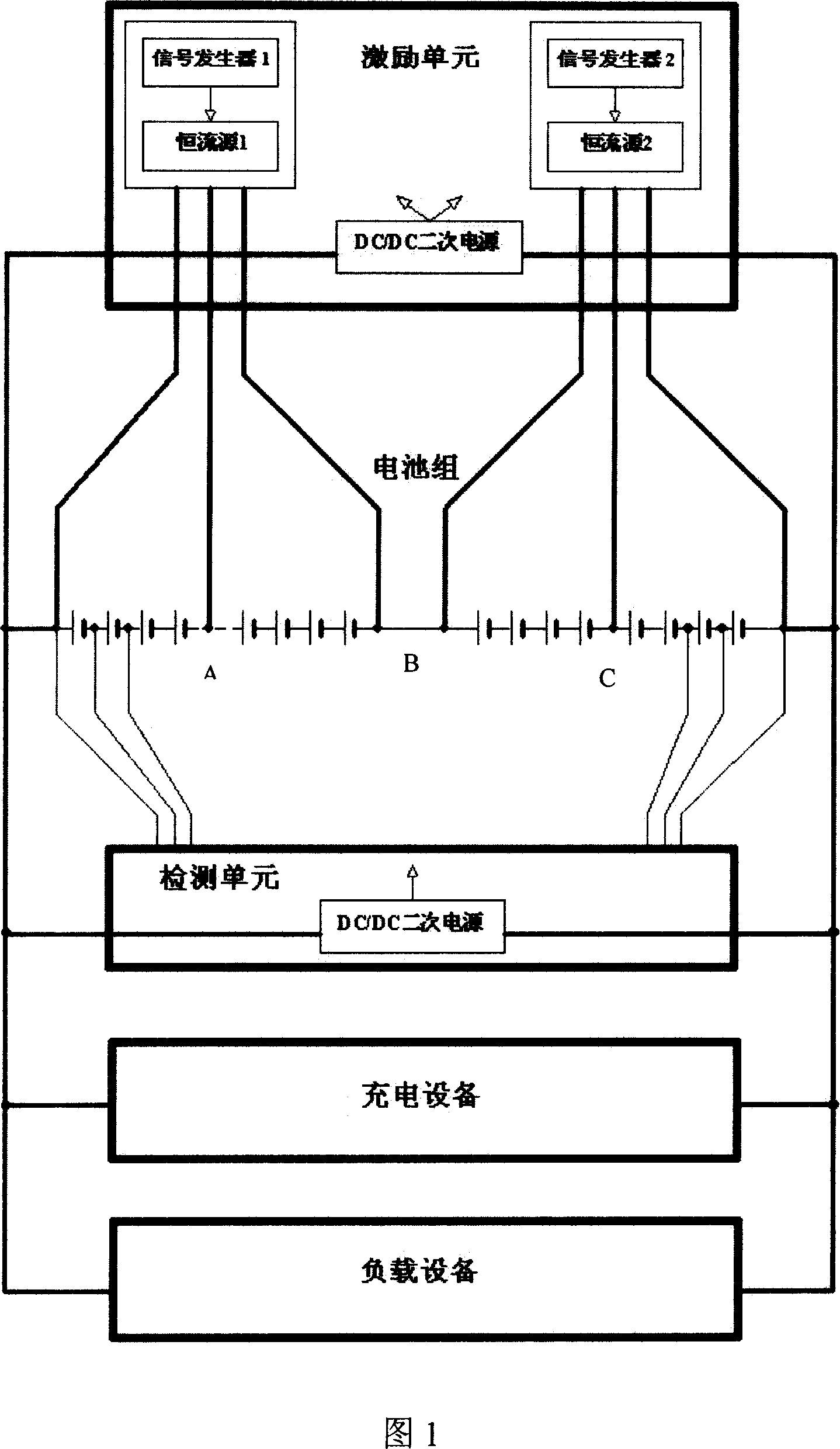
[0040]Embodiment 1: As shown in Figure 1, the battery internal resistance and deterioration state online monitoring system includes an excitation unit and a detection unit. The excitation unit is composed of two sets of signal generators and constant current sources. The current sine wave or rectangular wave signal is transmitted to the constant current source; among them, three segmentation points A, B, and C are set in the battery pack to divide the battery pack into four sections, and the signal generator is connected to the segmentation points A and B 1 and constant current source 1, connect the signal generator 2 and constant current source 2 at subsection points B and C, respectively measure the single batteries in the battery pack, and connect the total positive pole and the total negative pole of the battery The excitation unit, the excitation unit is used to generate a specific waveform and the peak-to-peak constant excitation current provides an excitation signal for ...
Embodiment 2
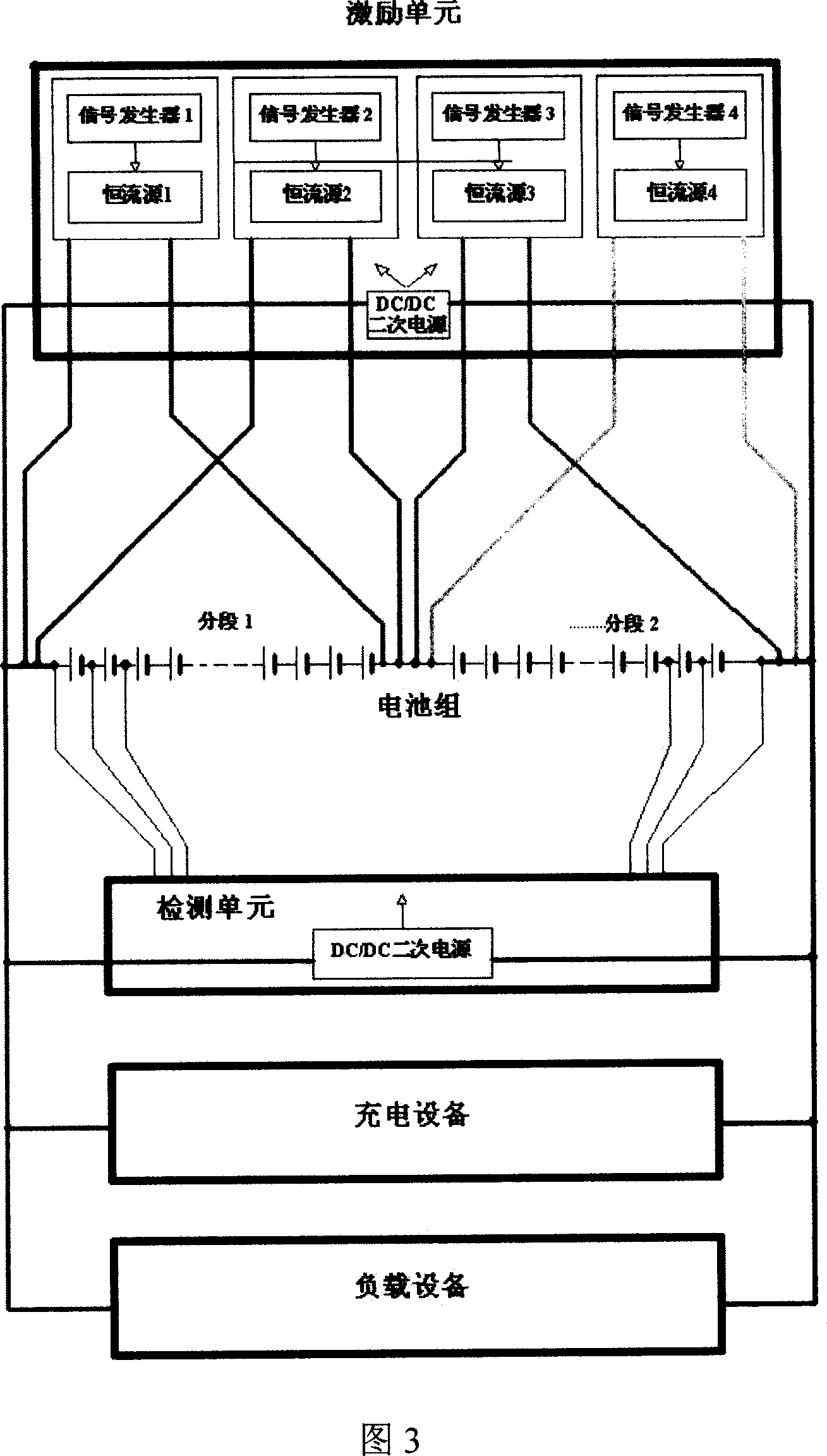
[0043] Embodiment 2: The on-line monitoring system for battery internal resistance and deterioration state as shown in Figure 3 includes an excitation unit and a detection unit. The excitation unit includes multiple sets of signal generators and constant current sources, and they are connected in parallel. The battery The group is divided into two or more sections; Figure 3 is divided into two sections, each section uses two signal generators and constant current sources, and two wires are drawn from the excitation unit to connect with the positive, midpoint and negative terminals of the section in the battery pack .
[0044] As shown in Figure 4, the schematic diagram of the excitation signal circuit when external excitation is added during the measurement process; according to the size of the excitation signal current required for the test and the number of cells in the test battery, the current circuit can be selected. The arc shown in the figure is The signal circuit when ...
PUM
 Abstract
Description
Claims
Application Information
 - Generate Ideas
- Intellectual Property
- Life Sciences
- Materials
- Tech Scout
- Unparalleled Data Quality
- Higher Quality Content
- 60% Fewer Hallucinations
Browse by: Latest US Patents, China's latest patents, Technical Efficacy Thesaurus, Application Domain, Technology Topic, Popular Technical Reports.
© 2025 PatSnap. All rights reserved.Legal|Privacy policy|Modern Slavery Act Transparency Statement|Sitemap|About US| Contact US: help@patsnap.com


